
Laser light emitting device having a mode scrambler for unifying light intensity distribution

a light intensity distribution and laser light emitting technology, which is applied in the direction of instruments, laser details, active medium materials, etc., can solve the problems deterioration of laser beam quality, and influence of non-uniform light intensity distribution on distance measurement accuracy, so as to achieve easy-to-use uniformity of light intensity distribution

Active Publication Date: 2017-07-18
KK TOPCON
View PDF10 Cites 1 Cited by
  • Summary
  • Abstract
  • Description
  • Claims
  • Application Information

AI Technical Summary

Benefits of technology

The mode scrambler ensures consistent light intensity distribution, improving the yield and reducing manufacturing costs of laser light emitting devices and surveying instruments by stabilizing light emission and reducing manufacturing complexity.

Problems solved by technology

Stress is generated inside the multi-mode fiber due to deformation and the generated stress exerts influence on an advancing condition of a laser beam which propagates the multi-mode fiber, causes non-uniformity of light intensity distribution and deteriorates a quality of the laser beam.
For instance, in a case were a laser light emitting device is used in a laser surveying instrument, non-uniformity of the light intensity distribution exerts influence on an accuracy of distance measurement because non-uniformity of the light intensity distribution gives influence on a photodetection intensity of a reflection light.
For this reason, an yield of the laser light emitting device is low, much cost for adjustment is needed, etc. and the laser light emitting device is of high cost.

Method used


Image

  • Laser light emitting device having a mode scrambler for unifying light intensity distribution
  • Laser light emitting device having a mode scrambler for unifying light intensity distribution
  • Laser light emitting device having a mode scrambler for unifying light intensity distribution

Examples


Embodiment Construction

[0022]Description will be given below on embodiments of the present invention by referring to the attached drawings.

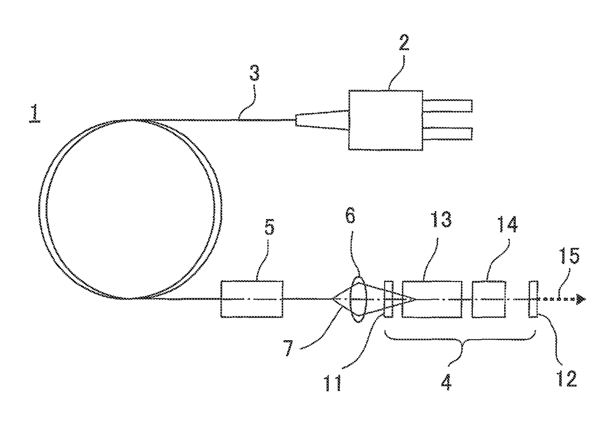
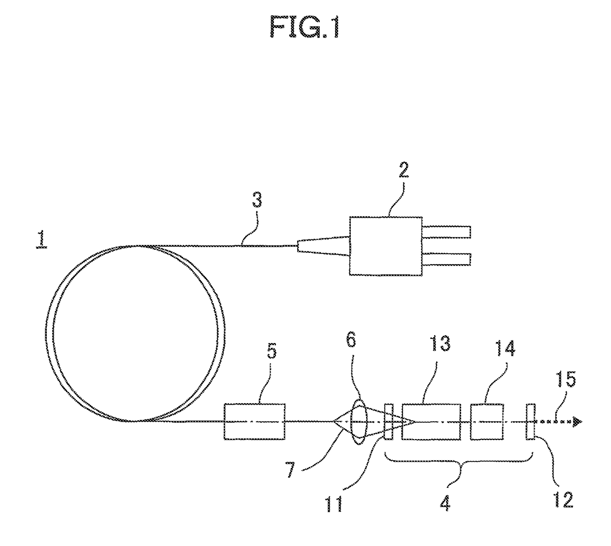
[0023]FIG. 1 shows a laser light emitting device 1 according to an embodiment of the present invention.

[0024]In FIG. 1, reference numeral 2 denotes a laser light emitter (LD light emitter) which emits a pump light, reference numeral 3 denotes an optical fiber (multi-mode fiber) which guides the pump light emitted from the LD light emitter 2 to a position as required. (e.g. an optical cavity 4). The optical fiber 3 is curved in a form of a coil or is treated as required such as bending, twisting, etc. to change a direction.

[0025]Further, a mode scrambler 5 is provided at a position as required of the optical fiber 3, preferably near an emitting end. At a position opposite to the emitting end of the optical fiber 3, a focus lens 6 is provided. The focus lens 6 focuses a pump light 7 emitted from the optical fiber 3 and makes the pump light 7 to enter the optical cavity 4...


PUM


Abstract

The invention provides a laser light emitting device, which comprises a laser light emitter for emitting a pump light, a resonator for emitting a laser beam by oscillating and amplifying the pump light and a multi-mode fiber for guiding the pump light emitted from the laser light emitter to the resonator, wherein a mode scrambler is provided on the multi-mode fiber, the pump light propagating the multi-mode fiber is stirred and a light intensity distribution is unified by the mode scrambler, and the pump light is entered to the resonator.

Description

BACKGROUND OF THE INVENTION[0001]The present invention relates to a laser light emitting device using a multi-mode fiber and a laser surveying instrument comprising the laser light emitting device.[0002]A pump light, emitted by a laser diode is entered into a cavity via a multi-mode fiber, and at the cavity, pumping is performed on the pump light. The pump light is resonated, amplified and outputted as a laser beam.[0003]The multi-mode fiber to guide the pump light to the cavity is subject to a deformation as required such as bending, twisting, etc. in the process of installing on a device or an instrument. Stress is generated inside the multi-mode fiber due to deformation and the generated stress exerts influence on an advancing condition of a laser beam which propagates the multi-mode fiber, causes non-uniformity of light intensity distribution and deteriorates a quality of the laser beam.[0004]For instance, in a case were a laser light emitting device is used in a laser surveying...

Claims


Application Information

Patent Timeline
Patent Type & Authority Patents(United States)
IPC IPC(8): H01S3/067G01S17/08H01S3/0941H01S3/094H01S3/16H01S3/117H01S3/115
CPCG01S17/08H01S3/06704H01S3/0941H01S3/094053H01S3/115H01S3/117H01S3/1611H01S3/1673
Inventor ENO, TAIZONAGANO, SHIGENORIYOSHINO, KEN-ICHIRO
Owner KK TOPCON
Learn More