Biometric sensor ring for continuous wear mobile data applications

a technology of mobile data and biometric sensors, applied in applications, instruments, diagnostic recording/measuring, etc., can solve the problem that monitoring is only possible in a laboratory setting, and achieve the effect of sufficient capacity energy storag

Active Publication Date: 2017-07-18
SENSTREAM
View PDF14 Cites 55 Cited by
  • Summary
  • Abstract
  • Description
  • Claims
  • Application Information

AI Technical Summary

Benefits of technology

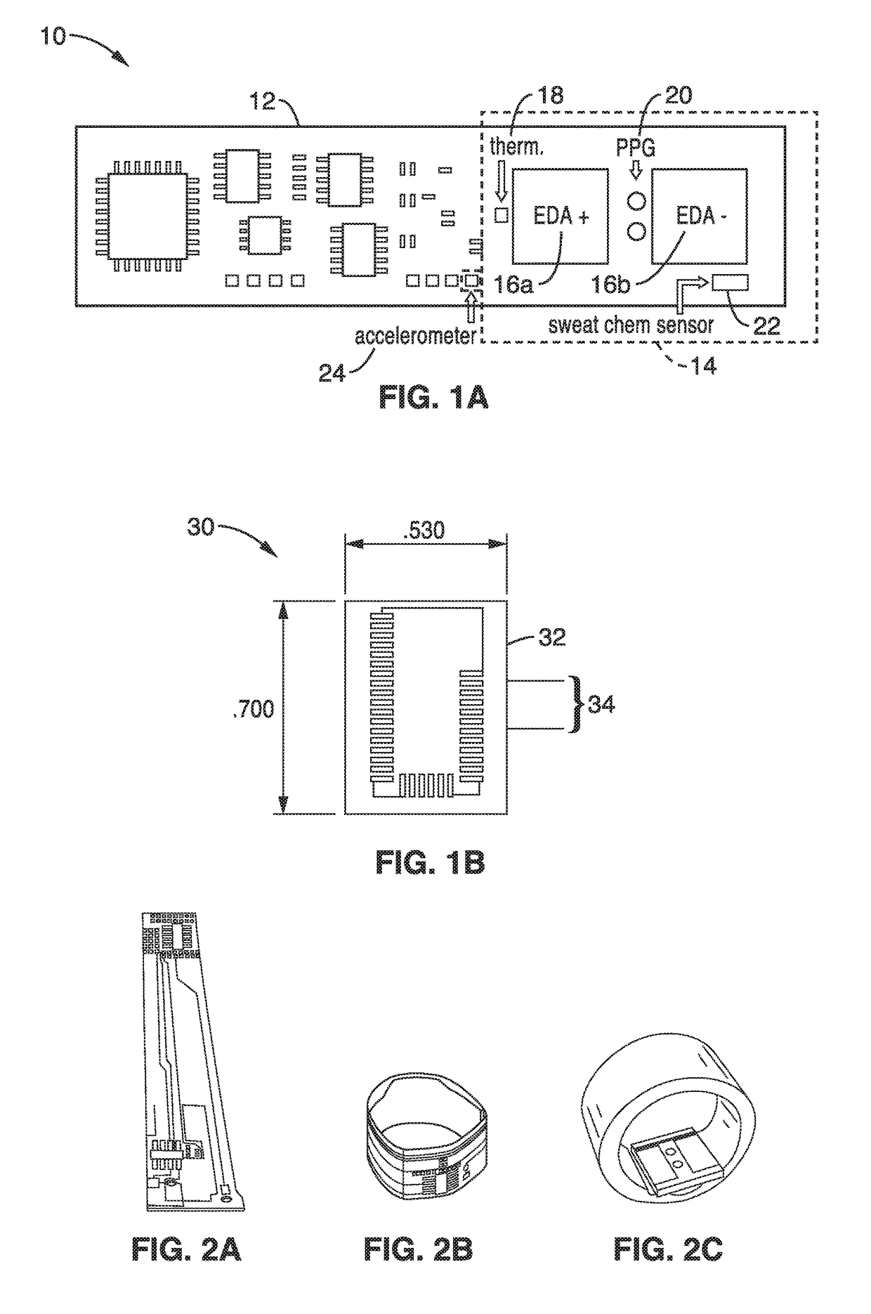
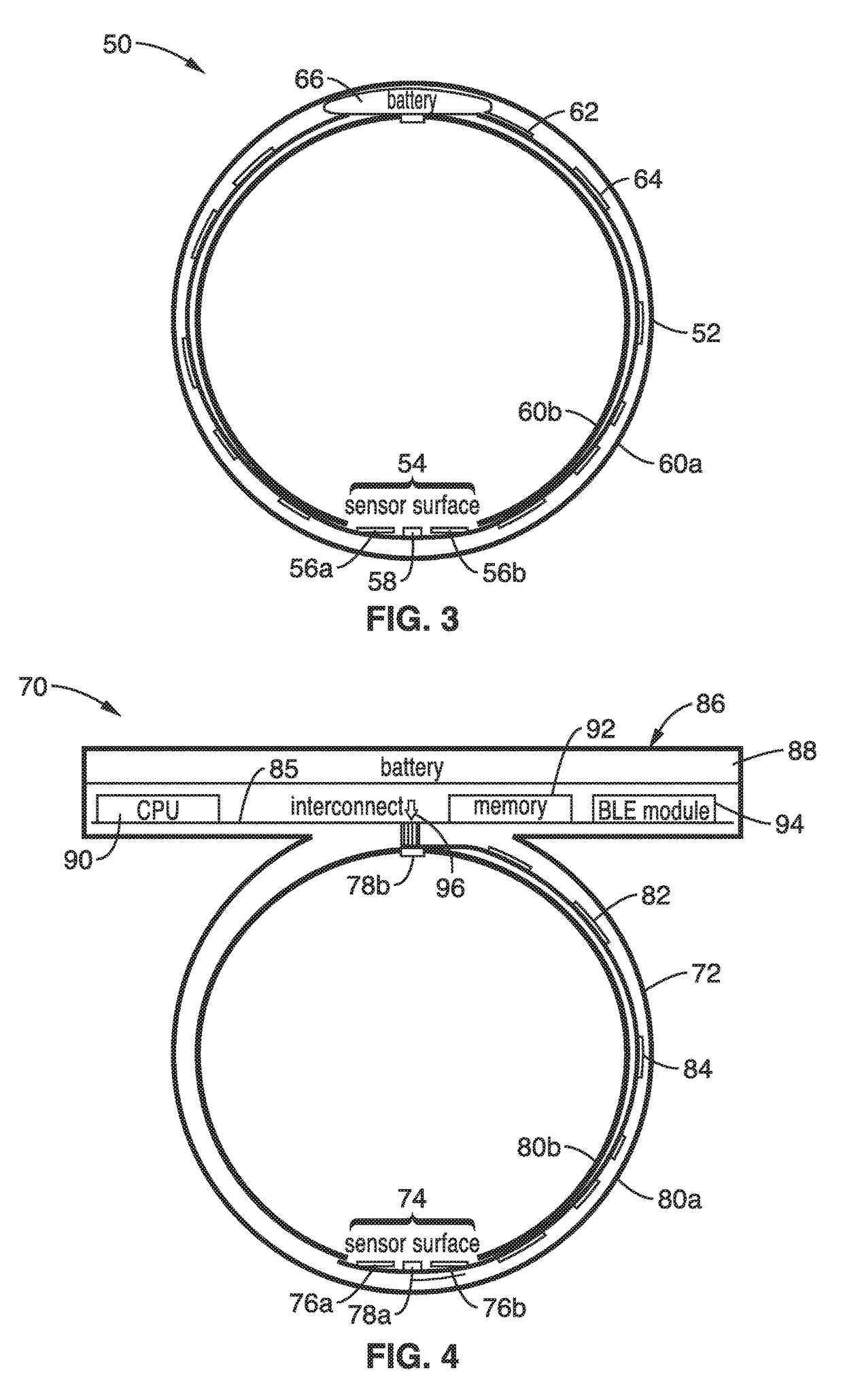
[0011]In contrast to the above, the present disclosure describes a ring form factor with mechanical and electronic provisions that allow for continuous wear (e.g., outside of the confines of a test environment, such as while performing everyday activities) and proper fit on fingers of different sizes. To produce quality biometric data, the biometric sensors must maintain proper skin contact on the finger. Toward that objective the present disclosure describes several embodiments for a sensor ring configured to assure a proper fit with a user's finger, or fingers, so that sensors are retained with proper skin contact and pressure.
[0012]Advantageously, various embodiments of the technology

Problems solved by technology

Presently ANS monitoring is only

Method used


Image

  • Biometric sensor ring for continuous wear mobile data applications
  • Biometric sensor ring for continuous wear mobile data applications
  • Biometric sensor ring for continuous wear mobile data applications

Examples


embodiment 190

[0055]FIG. 7 illustrates the ring embodiment 190 depicted in its proper placement on a finger having the sensor board on the bottom surface (palm side) of a hand 198.

[0056]FIG. 8 illustrates an example embodiment 210 of the biometric sensor ring which is configured to utilize the latest generation of biosensors, such as MC10 artificial skin, which is capable of supporting various types of chemical and molecular sensors. The ring housing 212 is seen on a finger 214 with circuits and sensors 218a, 218b along a flexible circuit 216. This embodiment takes advantage of the sensor input circuitry in the ring while greatly expanding the skin contact surface area for incorporating more sensor types as well as increasing the signal / noise for the EDA and PPG sensors. The artificial skin is unencumbering and disposable after one to two days.

[0057]FIG. 9 illustrates an example embodiment 190 depicting multiple rings 192, three in this example, joined by a signal line flex board 193 and retained...

embodiment 310

[0075]FIG. 19 illustrates a “C” ring embodiment 310 shown in a prototype form with housing 312 made from ¾ inch wide InstaMorph® plastic. In FIG. 19, the flex circuit 314 is seen joining sensor circuitry 316 on a circuit board end 318 to a BLE circuit 320 on the opposing circuit board end 322. Battery 324 is seen sandwiched between adhesive foam sections 326a, 326b, with wiring 328 attaching to circuit board section 322. A recharging connector 330 is also shown to allow recharging the battery without removing it from the sensor ring.

[0076]In creating this housing 312, the InstaMorph plastic was prepared from pellets that were first dissolved in hot water and then formed into 1 / 16 inch thick sheets that could be cut into ¼ inch strips. A 3¼ inch strip of plastic was then formed into a “C” shape by re-softening the material in warm water. At the same time, a shelf was formed to hold the BLE section of the flexboard at the top, and a lip was formed at the bottom to retain the edge of t...


PUM


Abstract

A biometric sensing apparatus for estimating the emotional state of a user. A self-contained biometric sensing ring is worn on the finger (or fingers) of the user during their normal activities. Biometric information is collected and sent wirelessly to the user's mobile device configured with application programming for analyzing and displaying the biometric information. The biometric ring is configured with sensors that the structure of the ring retains at a proper pressure against the finger of the user. The sensors comprise at least electrodermal response (EDR), photoplethysmograph (PPG), temperature, and acceleration. The ring has a self-contained power source, and is configured for adjustably fitting a wide range of users.

Description

CROSS-REFERENCE TO RELATED APPLICATIONS[0001]This application claims priority to, and the benefit of, U.S. provisional patent application Ser. No. 61 / 998,959 filed on Jul. 14, 2014, incorporated herein by reference in its entirety.STATEMENT REGARDING FEDERALLY SPONSORED RESEARCH OR DEVELOPMENT[0002]Not ApplicableINCORPORATION-BY-REFERENCE OF COMPUTER PROGRAM APPENDIX[0003]Appendix A referenced herein is a computer program listing in a text file entitled “SEN6468_05A_computer_program_listing_appendix_A.txt” created on Jul. 14, 2015 and having a 39 kb file size. The computer program code, which exceeds 300 lines, is submitted as a computer program listing appendix through EFS-Web and is incorporated herein by reference in its entirety.NOTICE OF MATERIAL SUBJECT TO COPYRIGHT PROTECTION[0004]A portion of the material in this patent document is subject to copyright protection under the copyright laws of the United States and of other countries. The owner of the copyright rights has no ob...

Claims


Application Information

Patent Timeline
IPC IPC(8): G09B19/00A61B5/0205A61B5/00G06F3/01A61B5/0402G08B21/04
CPCG09B19/00A61B5/0205A61B5/681G06F2203/0331A61B5/0402G08B21/0446G06F3/014G08B21/0453A61B5/0006A61B5/02055A61B5/6826A61B5/01A61B5/02405A61B5/02416A61B5/02438A61B5/0533A61B5/1118A61B5/145A61B5/4845A61B5/6802A61B5/6843A61B2560/0425G06F3/011G06F2203/011G09B19/0038G09B19/0092G09B23/28A61B5/318
Inventor LUSTED, HUGHROY, JASHOJITPROCTOR, DAVID W.
Owner SENSTREAM
Why Eureka
Try Eureka