Nanoelectroablation control and vaccination

a technology of electroelectroablation and control, applied in the field of electroelectroablation control and vaccination, can solve the problems of poor ablation around vessels and ducts, difficult control of the precise boundary of the ablation zone, lack of sharp boundary to the ablation zone, etc., to facilitate tumor antigen presentation, promote phagocytosis, and incite tumor antigen-specific cytotoxic t-cells

Active Publication Date: 2017-08-08
PULSE BIOSCI INC
View PDF9 Cites 26 Cited by
  • Summary
  • Abstract
  • Description
  • Claims
  • Application Information

AI Technical Summary

Benefits of technology

[0006]Immunogenic cell death has been characterized over the past 10 years as a cell death modality by which a series of damage-associated molecular patterns (DAMPs) are exhibited. The appearance of DAMPs may be essential for the stimulation of an immune response and general anticancer immunity in vivo. Traditionally, this cell death modality has been initiated by certain chemotherapeutic drugs such as anthracyclines, oxaliplatin, and mitoxantrone. A possible requirement for ICD is the combined action of reactive oxygen species (ROS) and endoplasmic reticulum (ER) stress. The ER stress mediated by Ca2+ release may lead to another important component of the signaling pathway in ICD, the translocation of calreticulin (CRT) from the ER to the cell surface to become an additional “eat me” signal for programmed cell death. Surface CRT binds to CD91 and CD69 on dendritic cells to promote phagocytosis, facilitating their tumor antigen presentation and incitement of tumor antigen-specific cytotoxic T-cells.

Problems solved by technology

RFA works by heating the tissue to hyperthermic levels for several minutes resulting in necrosis.
Two weaknesses of this technique are the lack of a sharp boundary to the ablation zone and poor ablation around vessels and ducts.
Since the spread of heat depends on the thermal conductivity of the tissue, it is difficult to control the precise boundary of this ablation zone.
In addition, the presence of heat sinks such as large vessels or ducts allows heat to be carried away from the tissue near the vessel and makes it difficult to reach the temperature required to ablate tissues in those regions.

Method used


Image

  • Nanoelectroablation control and vaccination
  • Nanoelectroablation control and vaccination
  • Nanoelectroablation control and vaccination

Examples


Embodiment Construction

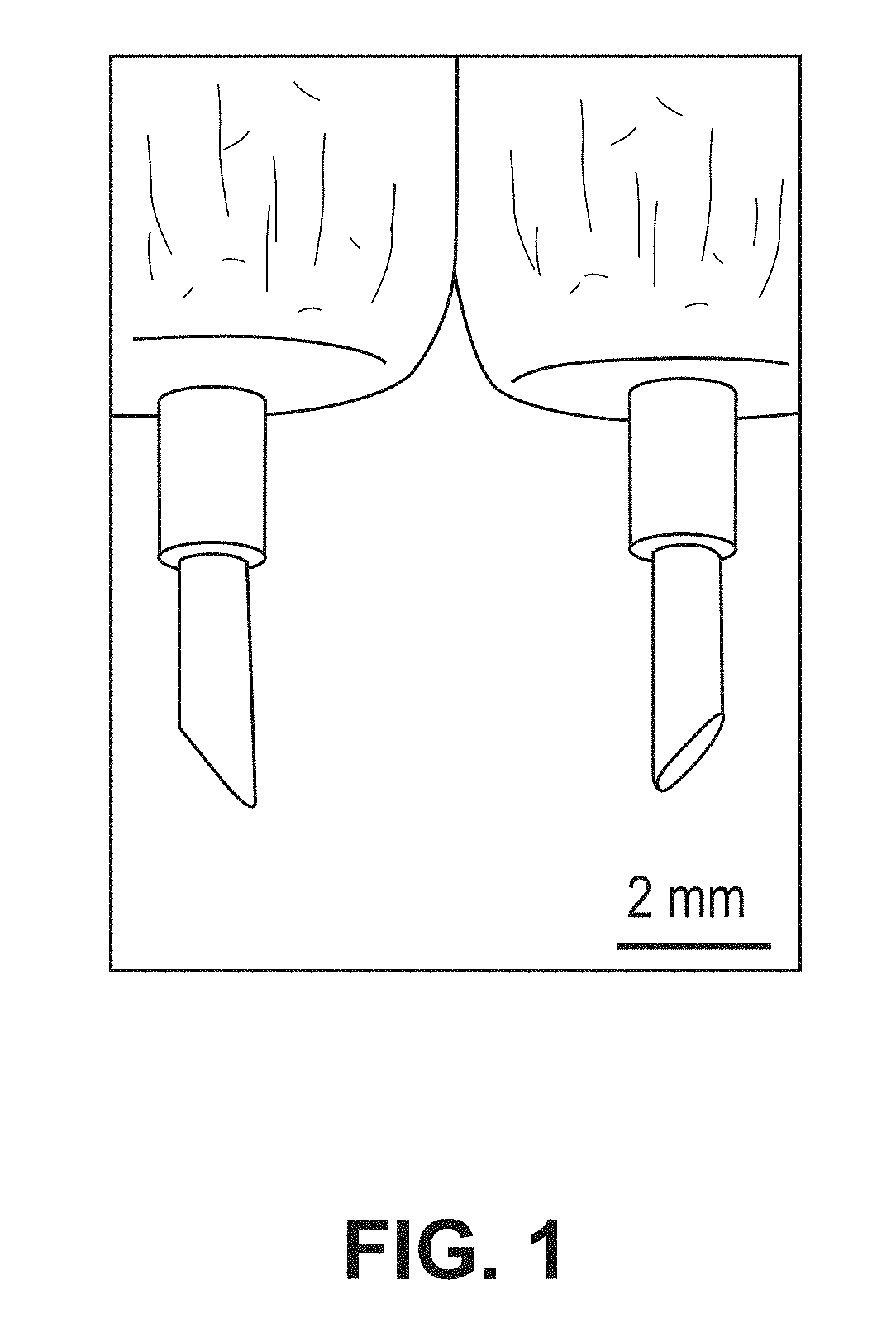
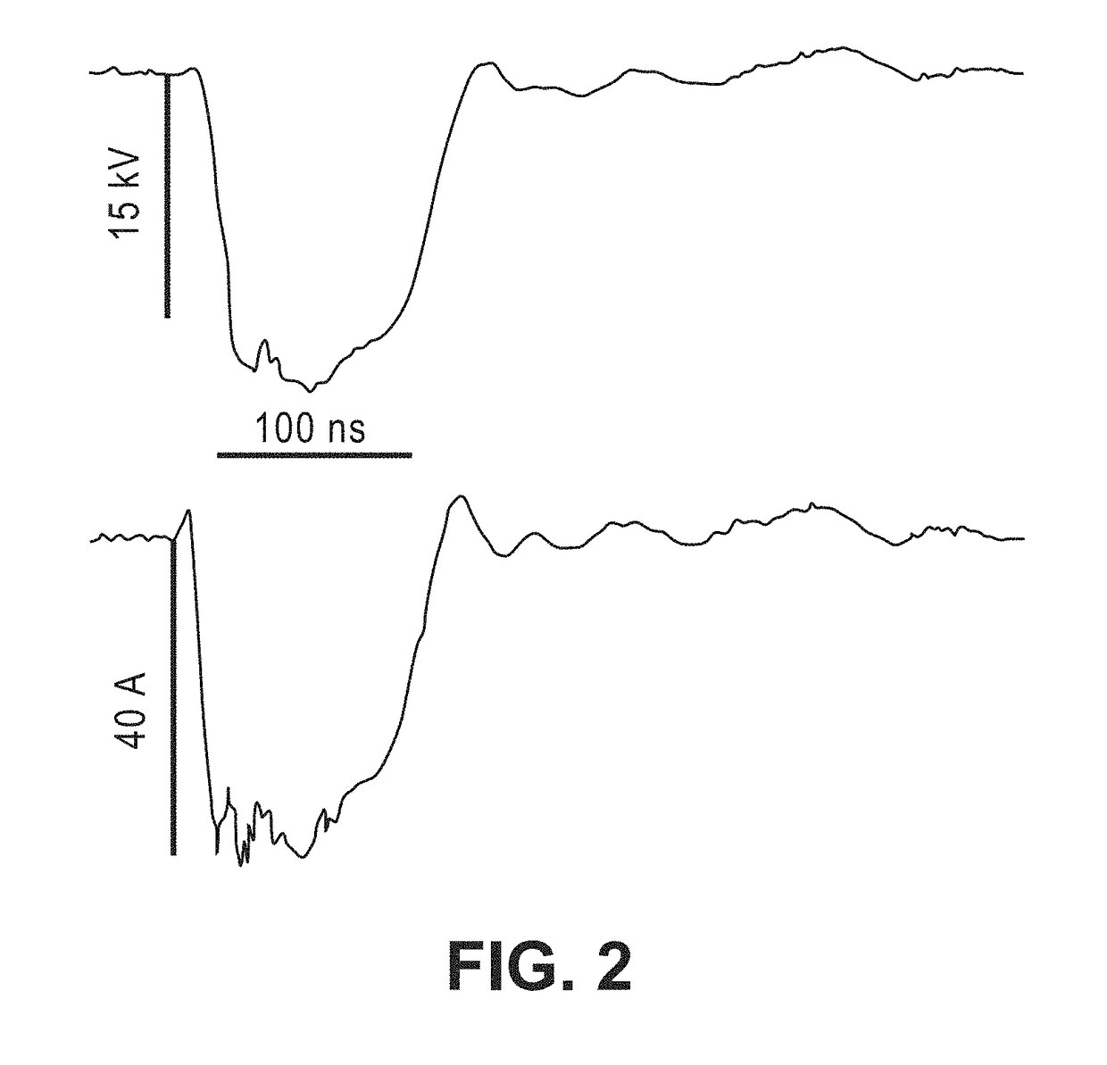
[0031]Precise ablation with a nanopulsed (sub-microsecond) multi-electrode can be realized by visualization of an imaginary contour line of a threshold value of an electric field surrounding the electrodes. A threshold value of about 12 kV / cm has been shown to produce a very sharp boundary between ablated and nonablated tissue.

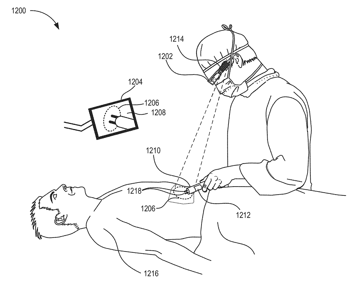
[0032]Visualization of the ‘critical’ boundary can assist a surgeon, researcher, or other operator. The visualization can be performed by a synthetic overlay onto a video image of the electrode on a display screen. The display screen can be affixed to glasses worn by the operator (e.g., GOOGLE Glass®), or it can be a separate screen. Alternatively, a projection device can project an image of contour lines onto a tumor that is to be ablated.

[0033]An instrument tracking system can detect a location and orientation of the instrument's electrodes. The instrument tracking system may be camera-based or use other sensors for detecting the electrodes.

[0034]For fine co...


PUM


Abstract

Techniques for treating a tumor and vaccinating against cancer are described. The techniques include treating the tumor by positioning electrodes over an interface between the tumor and non-tumor tissue and applying sub-microsecond pulsed electric fields. The positioning is facilitated by an imaginary contour line of a threshold value of the electric field. In an example, the imaginary contour line is overlaid over images that include the tumor such that the electrodes are properly positioned over the tumor. The techniques also include vaccinating against cancer by passing sub-microsecond pulsed electric fields through tumor cells of a subject sufficient to cause the tumor cells to express calreticulin on surface membranes. The tumor cells are extracted and introduced with the expressed calreticulin into the subject or another subject, thereby providing a vaccination.

Description

CROSS-REFERENCES TO RELATED APPLICATIONS[0001]This application claims priority to Provisional Patent Application No. 62 / 086,025, filed Dec. 1, 2014, by Richard Nuccitelli et al., and is entitled in whole or in part to that filing date for priority. The specification and drawings of Provisional Patent Application No. 62 / 086,025 are incorporated herein in its entirety by reference.STATEMENT AS TO RIGHTS TO INVENTIONS MADE UNDER FEDERALLY SPONSORED RESEARCH AND DEVELOPMENT[0002]This invention was made with government support under award numbers R01CA125722 and R44CA150484 awarded by the National Institutes of Health (NIH). The government has certain rights in the invention.BACKGROUND[0003]Hepatocellular carcinoma (HCC) is the third leading cause of cancer-related death worldwide and the ninth leading cause in the US. According to the International agency for Research on Cancer, HCC is the fifth most common cancer in men (523,000 cases per year with 7.9% of all cancer cases) and the sev...

Claims


Application Information

Patent Timeline
Patent Type & Authority Patents(United States)
IPC IPC(8): A61B18/00A61B90/00A61N1/40A61N1/32A61B1/04A61B34/20A61B18/14A61B6/03A61M37/00A61B34/10A61B6/12
CPCA61B18/1492A61B1/04A61B18/1477A61B34/20A61B90/37A61N1/326A61N1/40A61B6/03A61B6/12A61B2018/00273A61B2018/00529A61B2018/00577A61B2018/00613A61B2018/00642A61B2018/00892A61B2018/00904A61B2018/00982A61B2034/101A61B2034/107A61M2037/0007A61B1/00045A61B1/043A61B1/05A61B1/06A61B1/000094
Inventor NUCCITELLI, RICHARD LEEBERRIDGE, JON CASEYMALLON, ZACHARYKREIS, MARKATHOS, BRIANNUCCITELLI, PAMELA
Owner PULSE BIOSCI INC
Why Eureka
Try Eureka