Circuit for producing a laser diode control signal

a control signal and laser diode technology, applied in the field of circuits for producing laser diode control signals, can solve the problems of laser speckle, reduced image quality, and overall grainy image impression, and achieve the effects of improving image quality, reducing the proportion of reflected power, and great efficiency

Active Publication Date: 2017-09-05
ROBERT BOSCH GMBH
View PDF34 Cites 2 Cited by
  • Summary
  • Abstract
  • Description
  • Claims
  • Application Information

AI Technical Summary

Benefits of technology

[0008]The circuit according to the present invention, the laser diode receptacle according to the present invention, the image projector according to the present invention, the method according to the present invention for adjusting an RF modulator in a circuit for producing a modulated laser diode control signal from a laser diode control signal, as well as the manufacturing method have the advantage over the related art that an electronic attainment of the object of speckle reduction is created which has an optimum (power) adjustment of the RF modulator or the modulation signal based on the dependence of the configuration of the adjustment means on the laser diode operating information. Because of the adjustment, it is advantageously made possible to couple as large a part as possible of the electrical power of the laser diode control signal into the laser diode. The proportion of the reflected power is held to as low as possible. It is thereby possible to generate laser radiation from the available electric power, with great efficiency.
[0031]According to another preferred refinement, it is provided that the laser diode control signal is modulated using the modulation signal, the modulation signal having a modulation frequency greater than, or equal to 150 MHz and less than, or equal to 1.5 GHz, and preferably greater than, or equal to 200 MHz and less than, or equal to 1.0 GHz. For imaging projection systems, in which a laser beam writes the image pixel by pixel, there is yielded the lower limit for the modulation frequency from the product of the pixel number of the projected image and the image repetition frequency of the projection system. This lower limit for the modulation frequency is preferably still to be multiplied by an additional factor having the value 2 or greater. By this high-frequency modulation of the laser diode control signal, an especially efficient speckle reduction is advantageously possible.

Problems solved by technology

However, the image quality is reduced by so-called speckles.
This leads to an overall grainy image impression, the so-called laser speckle.
The disadvantage of this device is, however, that mechanically moved components are used, so that the implementation, particularly for mobile projectors, is comparatively costly.
In addition, miniaturization, which is necessary for mobile systems, is not possible.

Method used


Image

  • Circuit for producing a laser diode control signal
  • Circuit for producing a laser diode control signal
  • Circuit for producing a laser diode control signal

Examples


Embodiment Construction

[0040]In the various figures, identical parts have always been provided with the same reference symbols and are therefore usually labeled or mentioned only once.

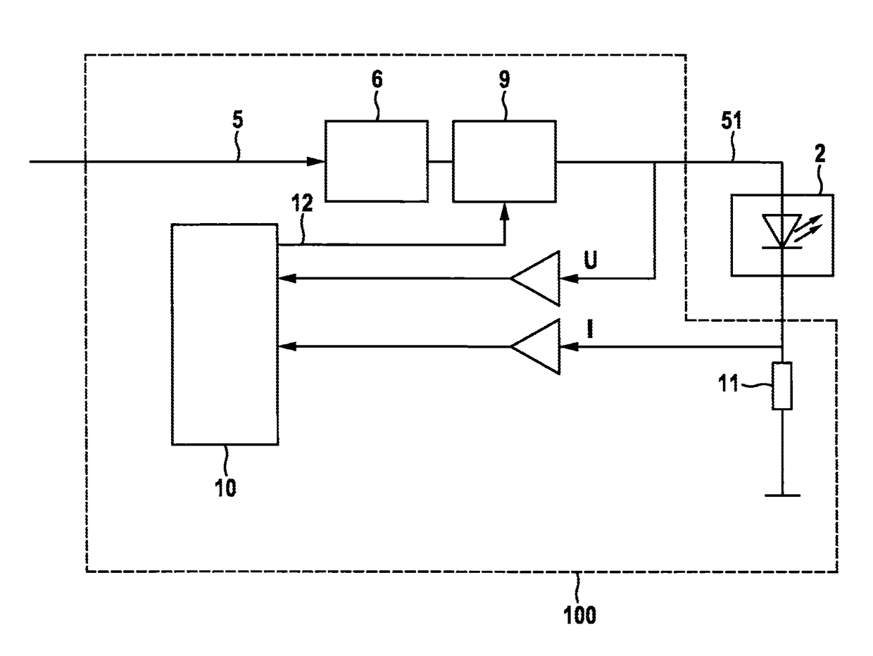
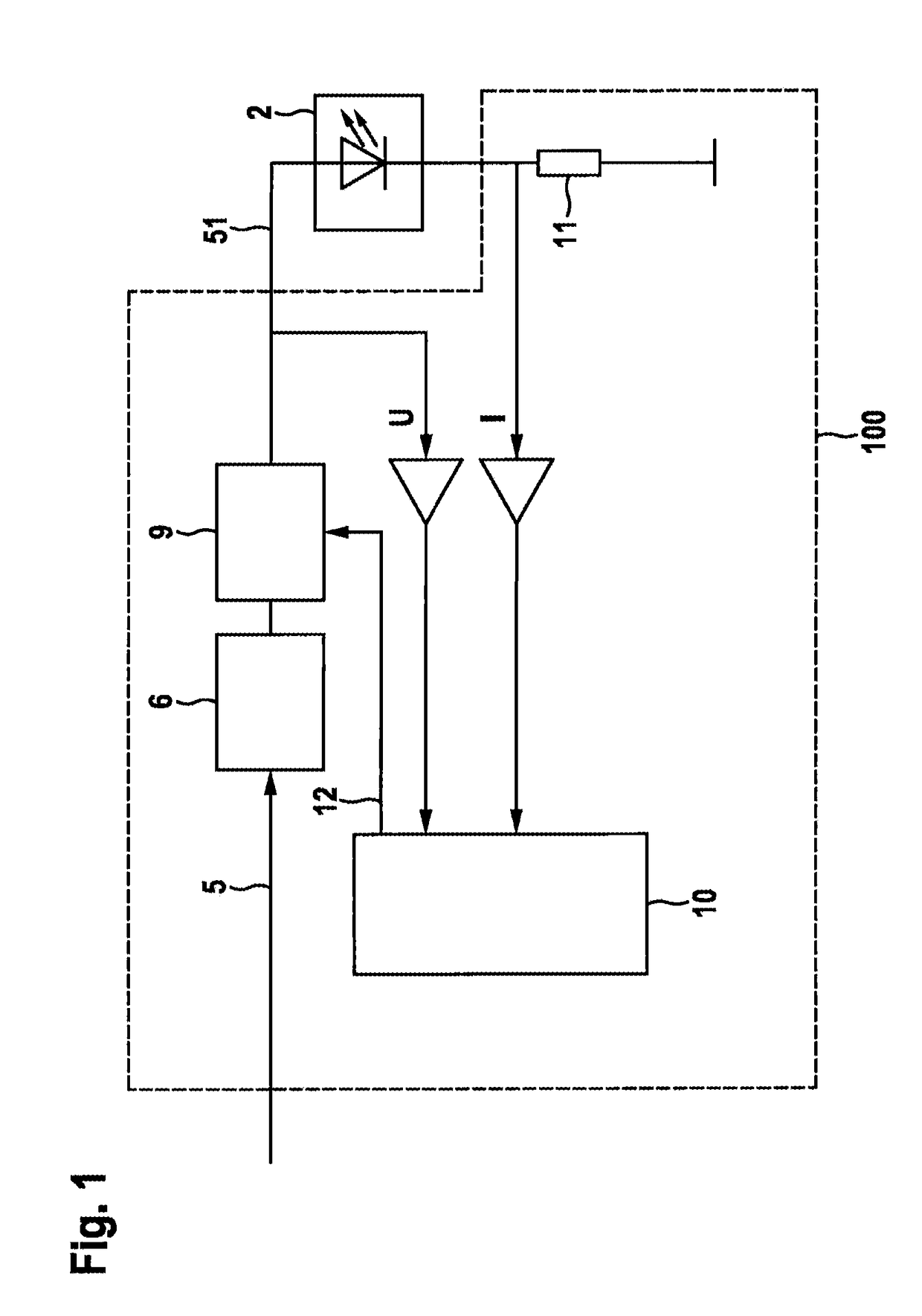
[0041]FIG. 1 schematically shows a circuit 100, according to an exemplary embodiment of the present invention, circuit 100 including the components situated in the area enclosed by the dashed line. At an input, circuit 100 has a laser diode control signal 5. Circuit 100 has an RF modulator 6, an adjustment circuit 9, a resistor 11 and an evaluation circuit 10. Laser diode control signal 5 may be an unmodulated signal or one that has already been modulated, a continuous-wave signal or an intermittent signal. RF modulator 6 generates a modulation signal, using which laser diode control signal 5 is modulated. Laser diode control signal 5 is thus converted by RF modulator 6 and the subsequent adjustment circuit 9 to a modulated laser diode control signal 51. Modulated laser diode control signal 51 actuates a laser diode 2. A las...


PUM


Abstract

A circuit is provided for generating a modulated laser diode control signal from a laser diode control signal, the circuit having an RF modulator for modulating the laser diode control signal with a modulation signal; the circuit having adjustment means for adjusting the RF modulator; the adjustment means being configured or configurable as a function of at least one laser diode operating information item. Furthermore, a laser diode receptacle is described as having such a circuit, a projector, particularly an image projector having such a laser diode receptacle, an image projector having such a laser diode receptacle and a laser diode, as well as a method for adjusting an RF modulator of such a circuit and a method for producing such a laser diode receptacle.

Description

FIELD OF THE INVENTION[0001]The present invention relates to a circuit for producing a laser diode control signal.BACKGROUND INFORMATION[0002]The use of laser sources, particularly in a laser-based image projection system, makes possible the production of images having a very large color space. However, the image quality is reduced by so-called speckles. Speckles are created when coherent light, such as laser light, hits a surface and is scattered there, which is the case, for example, when laser light impinges upon a projection screen. In this instance, at the point of observation, the light waves of all scattering centers are superposed on one another and destructive interferences occur, for one thing, in which the superposed light waves are mutually extinguished, whereby dark points are created in the point of observation, and for another thing, constructive interferences occur, in which superposing light waves are amplified, so that bright points of light are created. This leads...

Claims


Application Information

Patent Timeline
Patent Type & Authority Patents(United States)
IPC IPC(8): H01S5/062H01S5/065H01S5/068G03B21/20H04N9/31H01S5/042
CPCH01S5/06226G03B21/2053H01S5/0652H01S5/06808H04N9/3135H04N9/3161H01S5/0427H01S5/0622
Inventor SEIDEL, JUERGENFIESS, REINHOLDHASCH, JUERGENFREDERIKSEN, ANNETTEHILBERATH, THOMAS
Owner ROBERT BOSCH GMBH
Why Eureka
Try Eureka