Scanning real-time microfluidic thermocycler and methods for synchronized thermocycling and scanning optical detection

a real-time microfluidic thermocycler and optical detection technology, applied in the direction of fluorescence/phosphorescence, instruments, biochemistry apparatus and processes, etc., can solve the problems of inability to perform diagnostic analyses in vitro, no matter what, and can only be done with highly specialized equipment, which is both expensive and only operable by trained clinicians. achieve the effect of substantially uniform thermal conta

Active Publication Date: 2017-09-19
BECTON DICKINSON & CO
View PDF1151 Cites 54 Cited by
  • Summary
  • Abstract
  • Description
  • Claims
  • Application Information

AI Technical Summary

Benefits of technology

[0010]In some embodiments, the apparatus further comprises a heater plate, wherein the heater plate is positioned underneath the microfluidic cartridge when a cartridge is present in the receptacle. In some embodiments the heater plate comprises at least one of glass or quartz. In some embodiments, the aperture plate provides substantially uniform pressure across the area of the microfluidic cartridge when a cartridge is present within the receptacle. The substantially uniform pressure can facilitate substantially uniform thermal contact between the microfluidic reaction chambers and the heater plate. As such, in some embodiments, the aperture plate provide uniform pressure that can ensure that each of the plurality of reaction chambers or reactors in the microfluidic cartridge are in uniformly thermal contact or communication with a respective a plurality of heating elements located within the heater plate.

Problems solved by technology

At present, however, in vitro diagnostic analyses, no matter how routine, have become a bottleneck in patient care.
First, many diagnostic analyses can only be done with highly specialized equipment that is both expensive and only operable by trained clinicians.
This requires hospitals to send out samples for analyses to these locations, thereby incurring shipping costs and transportation delays, and possibly even sample loss or mishandling.
Second, the equipment in question is typically not available “on-demand” but instead runs in batches, thereby delaying the processing time for many samples as they must wait for a machine to reach capacity before they can be run.

Method used


Image

  • Scanning real-time microfluidic thermocycler and methods for synchronized thermocycling and scanning optical detection
  • Scanning real-time microfluidic thermocycler and methods for synchronized thermocycling and scanning optical detection
  • Scanning real-time microfluidic thermocycler and methods for synchronized thermocycling and scanning optical detection

Examples


Embodiment Construction

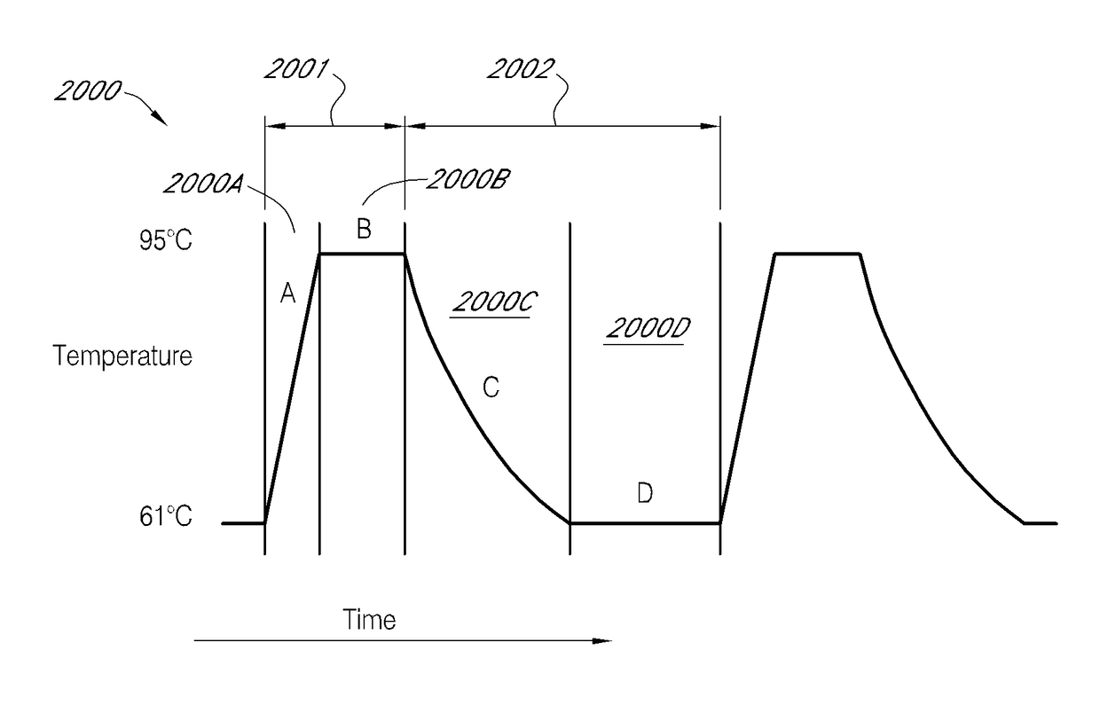
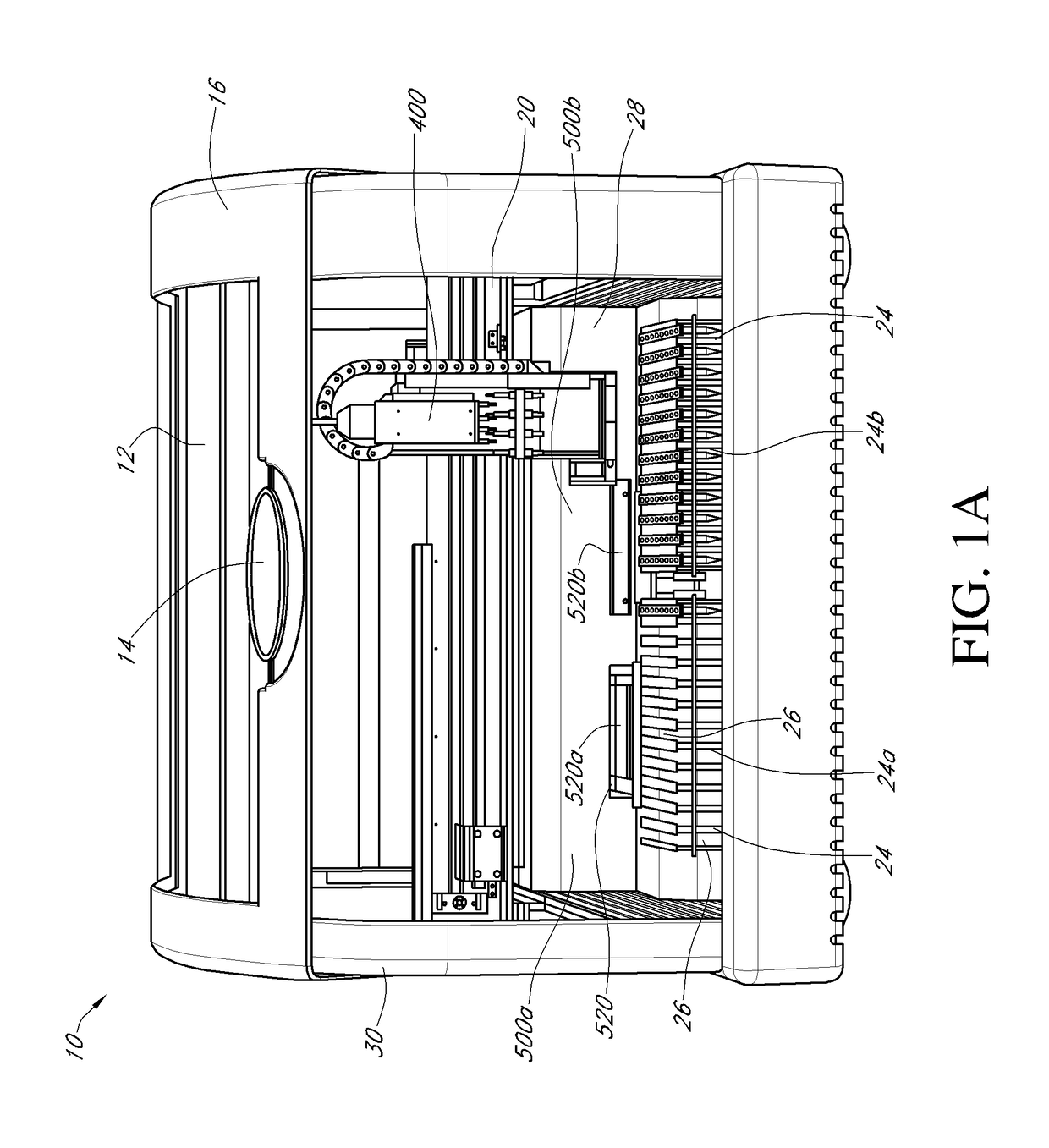
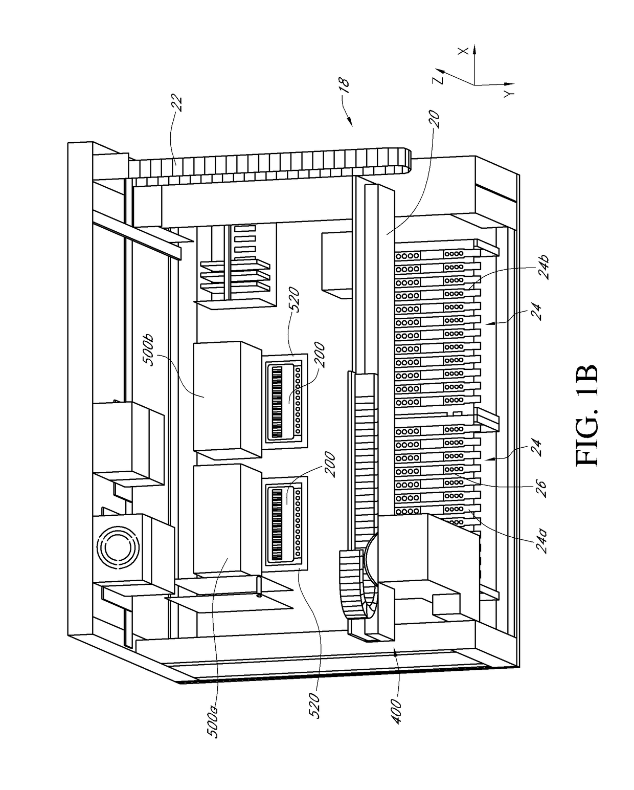
[0040]Certain of the present embodiments contemplate an apparatus, referred to herein as a thermocycler, which may consistently heat and analyze microfluidic chambers. Polynucleotide amplification, such as by real-time PCR, can be performed within the microfluidic chambers. In some embodiments, the thermocycler can be configured to perform individual thermocycling and detection protocols in a plurality of microfluidic reaction chambers within a microfluidic cartridge. The thermocycling can be used to amplify nucleic acids, e.g., DNA, RNA or the like, e.g., by real-time PCR or other nucleic acid amplification protocols described herein, within the microfluidic reaction chambers. The thermocycler may comprise a detector head, comprising a plurality of detector pairs, e.g., six or more detector head pairs, wherein each detector pair comprises a light-emitting source, e.g., an LED or the like, and a cognate photodiode. In some embodiments, each individual detector pair is configured to ...


PUM

PropertyMeasurementUnit
thicknessaaaaaaaaaa
volumesaaaaaaaaaa
volumesaaaaaaaaaa

Abstract

Systems and methods for performing simultaneous nucleic acid amplification and detection. The systems and methods comprise methods for managing a plurality of protocols in conjunction with directing a sensor array across each of a plurality of reaction chambers. In certain embodiments, the protocols comprise thermocycling profiles and the methods may introduce offsets and duration extensions into the thermocycling profiles to achieve more efficient detection behavior.

Description

CROSS-REFERENCE TO RELATED APPLICATIONS[0001]This application is a continuation of and claims the benefit of priority to co-pending International Patent Application No. PCT / US2012 / 033667, filed Apr. 13, 2012, entitled “SYNCHRONIZED THERMOCYCLING AND SCANNING OPTICAL DETECTION,” which claims the benefit of priority to U.S. Provisional Patent Application Ser. No. 61 / 476,175, filed on Apr. 15, 2011, entitled “SOFTWARE CONTROL PROCESS TO SYNCHRONIZE THERMOCYCLING AND SCANNING OPTICAL DETECTION” and U.S. Provisional Patent Application Ser. No. 61 / 476,167, filed on Apr. 15, 2011, entitled “6-COLOR SCANNING REAL-TIME MICROFLUIDIC THERMOCYCLER.” Each of the aforementioned applications is incorporated by reference herein in its entirety.TECHNICAL FIELD[0002]The systems and methods disclosed herein relate generally to the automated execution of nucleic acid amplification assays, such as Polymerase Chain Reaction (PCR), and in some instances real-time PCR, in a plurality of micro-fluidic react...

Claims


Application Information

Patent Timeline
Patent Type & Authority Patents(United States)
IPC IPC(8): C12P19/34C12Q1/68B01L7/00B01L9/00G01N35/02G01N21/64G01N35/00G01N21/27
CPCC12Q1/686B01L7/52B01L9/527G01N21/6428G01N21/6452G01N35/00693G01N35/026B01L2300/1822B01L2300/1827B01L2300/1838G01N21/274G01N21/278G01N2021/6419G01N2021/6421G01N2021/6441G01N2035/00366C12Q1/6806C12Q2563/107G01N33/53G01N35/00
Inventor GUBATAYAO, THOMAS CATALINOHANDIQUE, KALYANGANESAN, KARTHIKDRUMMOND, DANIEL M.
Owner BECTON DICKINSON & CO
Why Eureka
Try Eureka