High pressure, high flow rate tubing assembly and adapter for a positive displacement pump

a technology of tubing and positive displacement, which is applied in the direction of positive displacement liquid engines, flexible member pumps, machines/engines, etc., can solve the problems of high system pressure and chemical flow rate, high cost of operation of peristaltic hose pumps, and high corrosion resistance of assemblies, etc., to achieve high flow rate, increase drive efficiency, and increase the life of tubes

Active Publication Date: 2017-10-03
BLUE WHITE INDS
View PDF44 Cites 16 Cited by
  • Summary
  • Abstract
  • Description
  • Claims
  • Application Information

AI Technical Summary

Benefits of technology

[0010]The present inventions relate to pumps and tubing assemblies that are configured to pump fluids at high pressures and high flow rates. More particularly, the tubing assemblies can comprise multiple small diameter tubes that replace the traditional single large diameter hose in peristaltic pumps. In particular, embodiments disclosed herein can enable pumping against high pressures while providing a high flow rate, increased tube life, increased drive efficiency, lower replacement cost, lower energy consumption, cooler operating temperatures, and reduced operating and maintenance costs. Additionally, the tubing assemblies can comprise an interchangeable adapter system that may require less inventory cost and take up less inventory space. In some embodiments, the adapter system may include at least four mounts, at least four pump tubing grippers or locks, and at least four external system interface pieces. These pieces may be used interchangeably to fit a variety of tubing profiles, including single or dual tube or multiple lumen tubing, and customer requirements. In some embodiments, at least 64 different possible adapter system combinations may be made with an inventory of 12 different parts. All of these advantages are achieved while implementing designs that contrast with the traditional industry standard and knowledge.
[0013]In contrast to prior art techniques and applications, some embodiments disclosed herein reflect the realization that instead of using a single large diameter, large wall thickness, stiff tube or hose in a peristaltic pump, high pressures and high flow rates can be achieved with a peristaltic tube pump that uses a system of two or more tubes in which each tube has a smaller diameter and a specific relationship between tube wall thickness and tube durometer. As a result, the pump motor can be much smaller and more efficient than the traditional counterpart peristaltic hose pump that uses a large, stiff tube with a large wall thickness. Moreover, some embodiments are capable of pumping at high pressures and high flow rates while also resulting in increased tube life, increased drive efficiency, lower replacement cost, lower energy consumption, cooler operating temperatures, and reduced operating and maintenance costs. Further, embodiments disclosed herein can deliver fluid at pressures and flow rates that well exceed industry demands. For example, some embodiments can deliver fluid at pressures at or well above 100 PSI while achieving the industry-required flow rates.
[0014]Accordingly, some embodiments reflect realizations that in contrast to prior art peristaltic pumps and systems that use a single larger, stiff tube, a peristaltic pump and system using multiple smaller tubes can handle higher pressures, have a longer tube life than a single larger tube, have better memory retention than a single larger tube, and be more energy efficient than a single larger tube. Thus, while the industry has sought to increase fluid output by increasing the size of the tube and increasing the RPM of the motor, some embodiments disclosed herein reflect a contrary view and achieve superior results by using multiple tubes with smaller diameters.
[0015]For example, some embodiments disclosed herein reflect the realization that due to the continual cycles of compression and relaxation produced by each pass of the rotating cam, larger diameter tubes (hoses) flatten out sooner, causing a lower flow rate after a short amount of time. Some embodiments disclosed herein also reflect the realization that the ballooning effect can be minimized by using smaller tubes, and that a pump can generally overcome this phenomenon without challenges. Furthermore, some embodiments reflect the realization that smaller tubes tend to retain original memory for an extended amount of time (much longer than a larger diameter tube), resulting in higher accuracy and longer tube life. Moreover, some embodiments reflect the realization that unlike traditional small diameter tubing (which has not been used in high-pressure applications and have a low pressure rating), embodiments can be provided in which a small diameter tube has a desired tube wall thickness and / or desired tube durometer, and / or a desired ratio of tube wall thickness to tube durometer.
[0017]Additional embodiments disclosed herein illustrate a clamp-less adapter and tubing assembly for a peristaltic pump. Single or multi-lumen tubing assemblies may be manufactured with a variety of clamp-less adapters depending on customer requirements. The clamp-less adapter and tubing assembly takes up less space within the pump head housing than traditional clamped adapter and tube assemblies. In the case of multiple lumen tubing assemblies, the clamp-less style adapter assembly allows the tubes to be closer to each other, without interference from bulky metal clamps.

Problems solved by technology

These assemblies are susceptible to metal corrosion due to the leakage of fumes into the pump head housing.
However, system pressures and chemical flow rates often exceed the capabilities of existing peristaltic “tube” pumps.
Peristaltic hose pumps are considerably more expensive to operate (often three times more) because they use large, high-torque, high-horsepower AC drives.
Although peristaltic pumps have gained widespread popularity, the effectiveness of current peristaltic pumps is severely limited by the design of the tube or hose.
However, using a large diameter tube or hose at high pressure also requires a larger wall thickness in order to withstand the high pressure and avoid “ballooning.” Tubing in a peristaltic pump tends to expand or balloon at the outlet side where system pressure is exerted, and the effects of the ballooning and relaxing of the tubing can build up over time.
These challenges only increase as the required operating pressure is increased.
For example, as noted above, having a large wall thickness to achieve high pressures can cause additional load to the pump drive.
Tube diameter expansion (ballooning) can occur on pressure side of pump, which can require additional pump drive load to overcome tube diameter expansion (ballooning) and may result in early tube rupture.
In pumps having a glycerin-filled pump head (which is used to reduce friction and heat), tube rupture can cause glycerin to enter the fluid path and contaminate the system.

Method used


Image

  • High pressure, high flow rate tubing assembly and adapter for a positive displacement pump
  • High pressure, high flow rate tubing assembly and adapter for a positive displacement pump
  • High pressure, high flow rate tubing assembly and adapter for a positive displacement pump

Examples


second embodiment

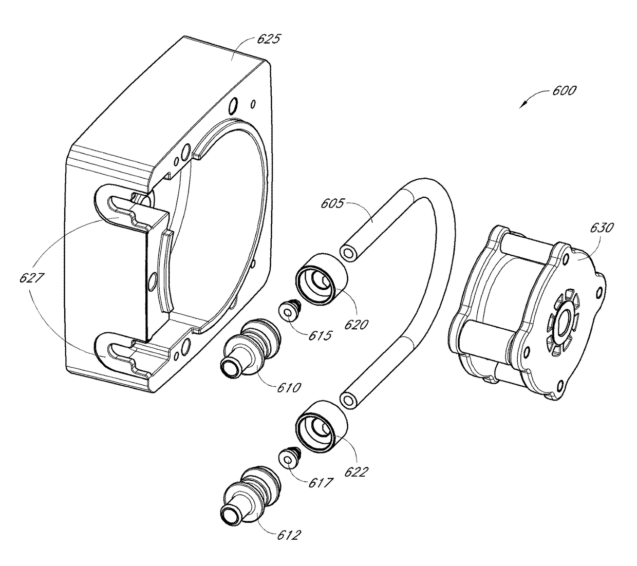
[0105]the assembly is shown in FIG. 27B. In this embodiment, the tube 205 is pressed through an opening in the tube mount 2702. A pump tubing gripper / lock 2712 is then inserted into the end of the tube 205. The pump tubing gripper / lock 2712 has a flange having a flange surface 2744 that abuts the end wall 2722 of the tube mount 2702. In some embodiments, friction between the tube 205 and the tube mount 2702 may hold the tube 205 in place without longitudinal movement. In other embodiments, adhesive or other suitable material to join the pump tubing gripper / lock 2712 to the tube mount 2702, that is, between the end wall 2722 and the flange surface 2744, may be required to prevent the tube 205 from longitudinal movement within the tube mount 2702.

third embodiment

[0106]FIG. 27C illustrates the assembly. In this embodiment, a tube 205 is pressed through an opening in the tube mount 2703. A pump tubing gripper / lock 2713 is then inserted into the end of the tube 205. In this embodiment, the pump tubing gripper / lock 2713 need not be adhered to the end wall 2735. Instead, the top flange surface 2714 of the pump tubing gripper / lock 2713 abuts against an end surface 2734 of the external system interface 2733. Similar to the embodiment shown in FIG. 26C, the tube mount 2703 abuts against the flange 2723 of the external system interface 2733.

[0107]In each shown in FIGS. 27A-C, an external system interface similar to the external system interfaces 123, 124, 125, 126 shown in FIG. 23 may be coupled to the tube mount by any of the methods discussed in greater detail above.

[0108]Embodiments of the tubing assemblies disclosed herein can be fabricated using a variety of materials, such as polymer materials, rubber, polyurethane, neoprene, tygothane, and ot...


PUM

PropertyMeasurementUnit
diameteraaaaaaaaaa
flow rateaaaaaaaaaa
flow rateaaaaaaaaaa

Abstract

A tubing and adapter assembly is provided that can comprise a plurality of tubes or lumens that can be disposed within a head of a peristaltic pump. The tubing assembly can provide a flow rate or volume capacity that is generally equal to or greater than that achieved with a comparable prior art tube while operating at higher pressures than that possible using the prior art tube. Further, in accordance with some embodiments, the tubing assembly can achieve a longer working life than a comparable prior art tube, and the load on the pump motor can be reduced such that the pump life is increased and / or a larger pump motor is not required to achieve such advantageous results.

Description

INCORPORATION BY REFERENCE TO ANY PRIORITY APPLICATIONS[0001]Any and all applications for which a foreign or domestic priority claim is identified in the Application Data Sheet as filed with the present application are hereby incorporated by reference under 37 CFR 1.57.[0002]This application claims the benefit of U.S. Provisional Patent Application No. 61 / 786,040, entitled “HIGH PRESSURE, HIGH FLOW RATE TUBING ASSEMBLY AND ADAPTER FOR A POSITIVE DISPLACEMENT PUMP,” filed on Mar. 14, 2013, which is hereby incorporated by reference in its entirety.BACKGROUND[0003]Field of the Invention[0004]The present inventions relate to tubing assemblies, and more specifically to tubing assemblies for use with peristaltic pumps.[0005]Description of the Related Art[0006]A peristaltic roller pump typically has two or more rollers, but may have other configurations. The rollers are generally spaced circumferentially evenly apart and are mounted on a rotating carrier that moves the rollers in a circle....

Claims


Application Information

Patent Timeline
Patent Type & Authority Patents(United States)
IPC IPC(8): F04B43/08F04B43/12
CPCF04B43/12F04B43/08Y10T29/49959
Inventor GLEDHILL, III, ROBERTNGUYEN, JOHN
Owner BLUE WHITE INDS
Why Eureka
Try Eureka