Method for liquefying natural gas with a mixture of coolant gas

a technology of coolant gas and natural gas, which is applied in the direction of lighting and heating apparatus, refrigeration machines, solidification, etc., can solve the problems of large equipment requirements, large footprint, and dangerous gases, and achieve the effects of reducing the total energy consumed by the process, and increasing the transfer of hea

Active Publication Date: 2017-10-03
SAIPEM SA
View PDF7 Cites 3 Cited by
  • Summary
  • Abstract
  • Description
  • Claims
  • Application Information

AI Technical Summary

Benefits of technology

[0033]An object of the present invention is to provide a natural gas liquefaction process of the type with no phase change in the refrigerant gas that is suitable for being installed on board a ship or a floating support and that presents improved energy efficiency, i.e. that minimizes the total energy consumed by the process in terms of kWh in order to obtain 1 tonne of LNG, and / or that presents increased transfers of heat in the heat exchangers, and / or that makes it possible to implement a liquefaction installation that is more compact and more efficient.

Problems solved by technology

Said first cycle type with a change of phase is generally used in installations on land and it requires a large amount of equipment and occupies a large footprint.
In addition, the refrigerant fluids, generally in the form of mixtures, are constituted by butane, propane, ethane, and methane, which gases are dangerous since in the event of a leak they run the risk of leading to substantial fires or explosions.
The complexity of those installations comes from the fact that in those stages where the refrigerant fluid is in the liquid state, and more particularly in separators and in connection pipes, it is appropriate to install gravity collectors in order to bring the liquid phase together and direct it to the cores of heat exchangers where it vaporizes on coming into contact with the methane for cooling and liquefying in order to obtain LNG.
Managing a process with a phase change involving a liquid phase of the refrigerant fluid would then be extremely difficult, even for small movements of the floating support, and indeed practically impossible for extreme movements, whereas stationary installations on land do not face the problem of movements.
Since the mixture is flowing at lower pressure, heat exchange requires greater flow rates and thus pipes of larger diameters and heat exchangers of greater areas, thereby contributing to increasing the cost and the overall size of the installation and reducing the overall thermodynamic efficiency of the process.

Method used


Image

  • Method for liquefying natural gas with a mixture of coolant gas
  • Method for liquefying natural gas with a mixture of coolant gas
  • Method for liquefying natural gas with a mixture of coolant gas

Examples


Embodiment Construction

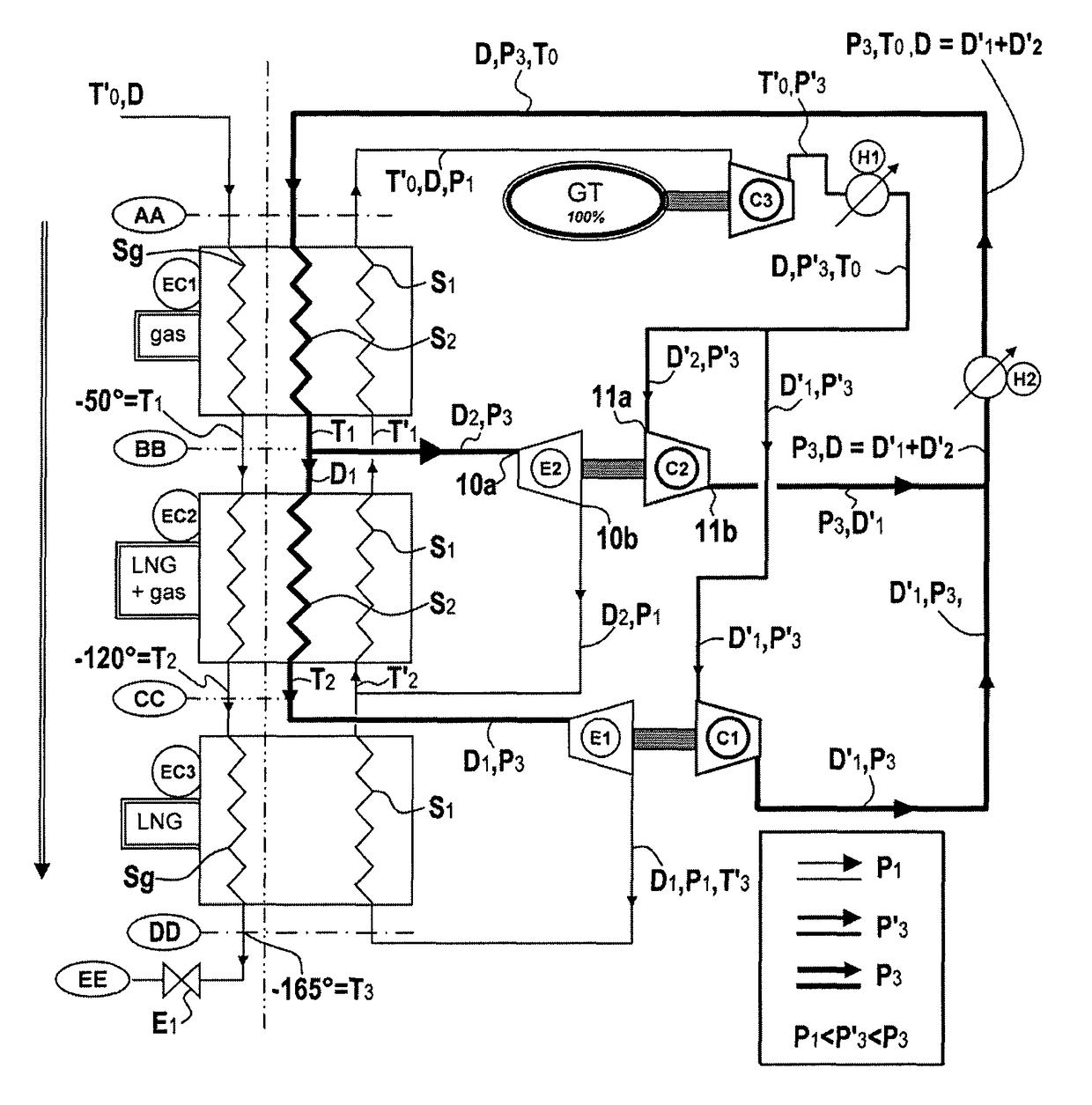
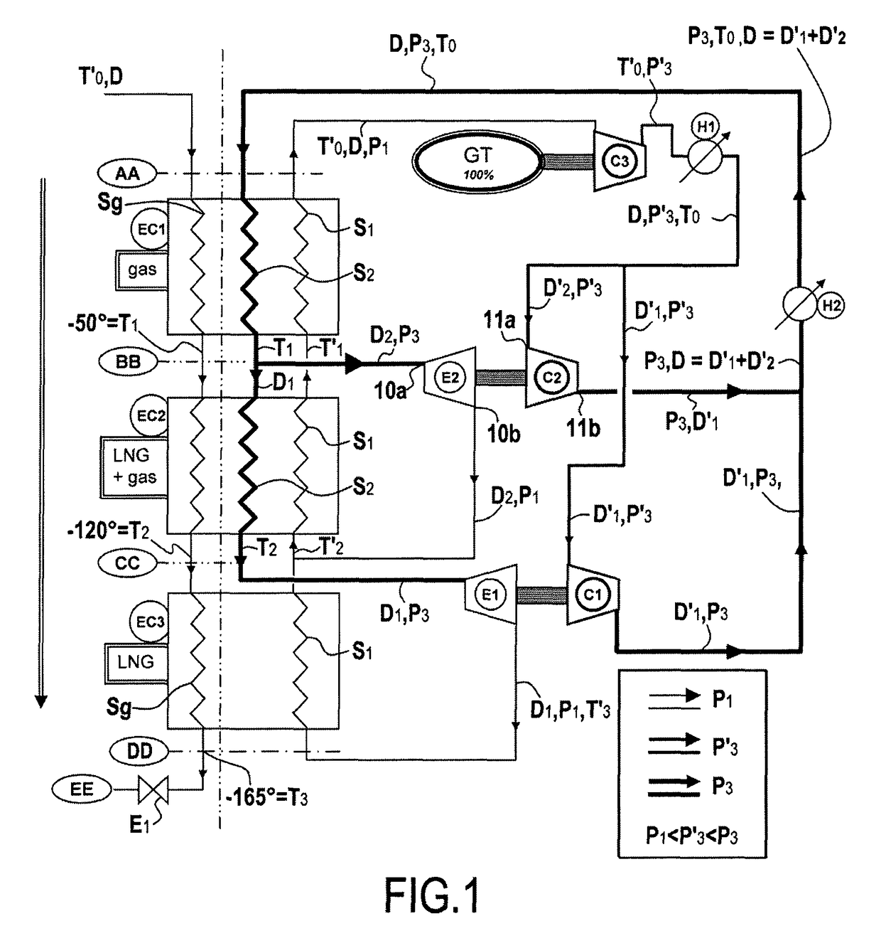
[0133]FIG. 1 is a process flow diagram (PFD) for the standard double loop process without phase change using nitrogen as the refrigerant gas. The process uses compressors C1, C2, and C3, expanders E1 and E2, intermediate coolers H1 and H2, and cryogenic heat exchangers EC1, EC2, and EC3. In known manner, the heat exchangers are constituted by at least two circuits that are juxtaposed but that do not communicate with each other in terms of said fluids, the fluids flowing in said circuits exchanging heat all along their paths within such a heat exchanger. Numerous types of heat exchanger have been developed in various industries and in the context of cryogenic heat exchangers, two main types predominate: firstly coiled heat exchangers; and secondly brazed aluminum plate heat exchangers, known as “cold box” heat exchangers.

[0134]Heat exchangers of this type are known to the person skilled in the art and they are sold by the suppliers Linde (France) or Five Cyrogénie (France). Thus, all...


PUM

PropertyMeasurementUnit
energyaaaaaaaaaa
pressureaaaaaaaaaa
pressureaaaaaaaaaa

Abstract

A method for liquefying a natural gas primarily including methane, preferably at least 85% of methane, the other components essentially including nitrogen and C2-C4 alkanes, in which the natural gas to be liquefied is liquefied by circulating at a pressure P0 no lower than the atmospheric pressure (Patm), P0 preferably being higher than the atmospheric pressure, in at least one cryogenic heat-exchanger (EC1, EC2, EC3) by a counter-current closed-circuit circulation in indirect contact with at least one stream of coolant gas remaining in the compressed gaseous state at a pressure P1 that is entering the cryogenic heat-exchanger at a temperature T3′ that is lower than T3, T3 being the liquefaction temperature of the liquefied natural gas at the pressure P0 at the output of said cryogenic exchanger, characterized in that the coolant gas includes a mixture of nitrogen and at least one other component selected from among neon and hydrogen.

Description

CROSS REFERENCE TO RELATED APPLICATIONS[0001]This is a U.S. national stage of application No. PCT / FR2012 / 051426, filed on Jun. 22, 2012. Priority is claimed on France Application No. FR1155593, filed Jun. 24, 2011, the content of which is incorporated herein by reference.FIELD OF THE INVENTION[0002]The present invention relates to a process for liquefying natural gas in order to produce liquefied natural gas (LNG). Still more particularly, the present invention relates to liquefying natural gas comprising a majority of methane, preferably at least 85% methane, with the other main constituents being selected from nitrogen and C-2 to C-4 alkanes, i.e. ethane, propane, and butane.[0003]The present invention also relates to a liquefaction installation on board a ship or a floating support at sea, either on the open sea or in a protected zone such as a port, or indeed an installation on land for small or medium natural gas liquefaction units.BACKGROUND OF THE INVENTION[0004]With an insta...

Claims


Application Information

Patent Timeline
Patent Type & Authority Patents(United States)
IPC IPC(8): F25J1/00F25J1/02F25B9/06C09K5/04
CPCF25J1/0022C09K5/041C09K5/042F25B9/06F25J1/005F25J1/0072F25J1/0097F25J1/0204F25J1/0212F25J1/0254F25J1/0283F25J1/0287F25J1/0288C09K2205/13C09K2205/132F25J2270/16F25J2230/20
Inventor BONNISSEL, MARCDU PARC, BERTRANDZIELINSKI, ERIC
Owner SAIPEM SA
Why Eureka
Try Eureka