Optoelectronic switch

a technology of optoelectronic switch and switch body, applied in the field of optoelectronic switch, can solve the problems of large device and inability to scale, and achieve the effects of reducing the number of components, simplifying the connectivity within the switch, and great switch functionality

Active Publication Date: 2017-10-03
ROCKLEY PHOTONICS LTD
View PDF17 Cites 2 Cited by
  • Summary
  • Abstract
  • Description
  • Claims
  • Application Information

AI Technical Summary

Benefits of technology

[0008]In this way, the optoelectronic switch of the present invention provides a greater switch functionality by employing a concentrator function within the DRM. This enables alternative switch architectures involving a reduction in the component count within the optoelectronic switch as well as simplifying the connectivity within the switch.
[0009]Scheduling algorithms may be chosen to implement Virtual output queuing. Virtual output queueing enables an improved throughput performance, addressing “head-of-line blocking” that can arise in prior art systems.
[0038]When operated as a packet switch, the DRM must contain packet processing and packet buffering capabilities. There are two directions, client-to-fabric, and fabric-to-client, and the DRM handles these two cases differently. When a DRM receives a packet from a client input port, it processes the packet to determine which output DRM the packet needs to be transmitted to, buffers the packet until the DRM is able to retransmit the packet over the single fabric output port. When a DRM receives a packet from another DRM over its fabric input port, it retransmits the packet over one of its client output ports. Like in the circuit switch use case, the DRM is controlled using via an external control input. However, for the packet switch use case, the DRM also provides information about packets stored in its buffers, so that a switch arbiter can make control decisions.

Problems solved by technology

The switch of U.S. Pat. No. 8,792,787 is a large device and is not scalable.

Method used


Image

  • Optoelectronic switch
  • Optoelectronic switch
  • Optoelectronic switch

Examples


Embodiment Construction

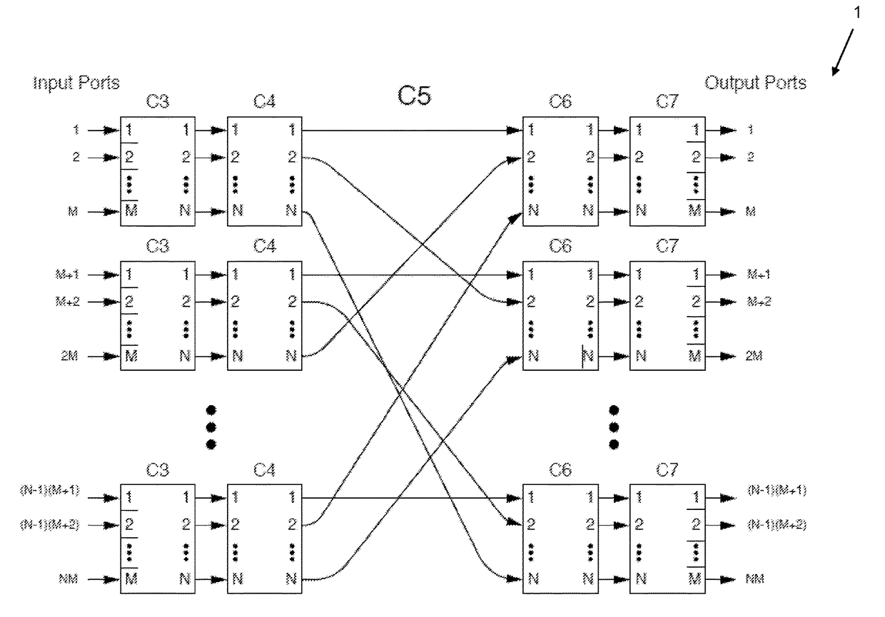
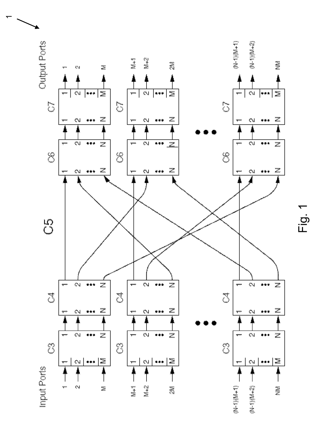
[0052]FIG. 1 shows an optoelectronic switch according to the present invention. The switch takes the form of an NM-port unfolded optoelectronic switch constructed with a DRM-AWG-AWG-DRM architecture, where N is the number of DRMs and M is the number of client facing input / output port pairs on each DRM.

[0053]The optoelectronic switch 1 comprises a first plurality of DRMs C3, a pre-mesh AWG stage C4, a full-mesh fabric C5, a post mesh AWG stage C6, and a second plurality of DRMs C7.

[0054]The input ports of each of the first plurality of DRMs C3 are configured to receive optical signals from the input ports of the optoelectronic switch. The outputs of the first plurality of DRMs C3 are optically connected to the inputs of the pre-mesh AWG stage; the outputs of the pre-mesh AWG stage are optically connected to the inputs of the optical full-mesh fabric C5, the outputs of the full mesh fabric are optically connected to the inputs of the post-mesh AWG stage, and the outputs of the post-me...


PUM


Abstract

An optoelectronic switch comprising: a first plurality of detector remodulators (DRMs) (C3, D1), each DRM having an integer number M of optical inputs and an integer number N of optical outputs; a second plurality of DRMs (C7, D5), each DRM having N optical inputs and M optical outputs; a passive optical switch fabric (C4+C5+C6, D2+D3+D4) connecting the N optical outputs of each of the first plurality of DRMs with the N optical inputs of each of the second plurality of DRMs, the path of an optical signal through the optical switch fabric depending upon its wavelength; wherein each DRM (C3, D1) of the first plurality of DRMs is configured to act as a tunable wavelength converter to select the desired path of an optical signal through the optical switch fabric (C4+C5+C6, D2+D3+D4); and wherein each of the first plurality of DRMs (C3, D1) includes a concentrator, the concentrator configured to aggregate optical signals received from any of the M inputs of that DRM and to buffer them according to the one of the plurality of second DRMs (C7, D5) that includes their destination port.

Description

CROSS-REFERENCE TO RELATED APPLICATIONS[0001]This application is a continuation-in-part of U.S. patent application Ser. No. 14 / 639,041, filed Mar. 4, 2015. This application also claims priority to U.S. Provisional Patent Application Ser. No. 62 / 152,696, filed Apr. 24, 2015, and U.S. Provisional Patent Application Ser. No. 62 / 057,818, filed Sep. 30, 2014. This application also claims priority to Great Britain Application No. GB1506729.1, filed Apr. 21, 2015. All of the above applications are incorporated by reference in their entirety.FIELD OF THE INVENTION[0002]The present invention relates to an optoelectronic switch, more particularly to an optoelectronic switch comprising a passive optical switch fabric and detector remodulators which act as tunable wavelength convertors, the detector remodulators including a concentrator.BACKGROUND OF THE INVENTION[0003]The present and continuing increase in data traffic volumes and the requirement for speed of switching and reduced energy consu...

Claims


Application Information

Patent Timeline
Patent Type & Authority Patents(United States)
IPC IPC(8): G02B6/35H04J14/02H04L12/933H04Q11/00
CPCH04L49/10G02B6/356H04J14/0212H04J14/0256H04Q11/0005H04Q11/0071H04Q2011/006H04Q2011/0032G02B6/4296H04L49/112H04L49/111
Inventor RICKMAN, ANDREWFARRINGTON, NATHAN
Owner ROCKLEY PHOTONICS LTD
Why Eureka
Try Eureka