Carbon nanotube assembly and viscoelastic body using same

a carbon nanotube and aggregate technology, applied in the direction of aligned nanotubes, transportation and packaging, grading, etc., can solve the problems of difficult handling of related-art viscoelastic bodies and difficult selective picking of particles having a specified particle diameter, and achieve excellent handling ability and small tack

Active Publication Date: 2017-10-24
NITTO DENKO CORP
View PDF31 Cites 2 Cited by
  • Summary
  • Abstract
  • Description
  • Claims
  • Application Information

AI Technical Summary

Benefits of technology

[0020]According to one embodiment of the present invention, it is possible to provide the material for a viscoelastic body that has small tack, is excellent in handleability and is capable of selectively picking a particle having a specified particle diameter. It is also possible to provide the viscoelastic body using such material.

Problems solved by technology

However, in a related-art viscoelastic body, it is difficult to selectively pick a particle having a specified particle diameter from a particle group with a large particle diameter distribution.
In addition, the related-art viscoelastic body is difficult to handle because it easily adheres to a smooth surface owing to its strong tack.

Method used


Image

  • Carbon nanotube assembly and viscoelastic body using same
  • Carbon nanotube assembly and viscoelastic body using same

Examples


first preferred embodiment

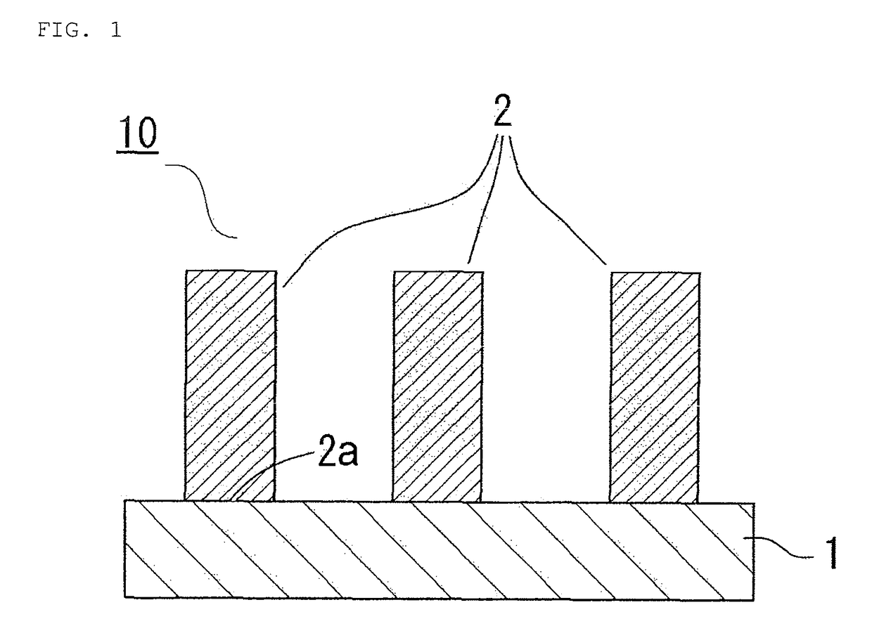
[0024]A carbon nanotube aggregate according to a preferred embodiment (hereinafter sometimes referred to as “first preferred embodiment”) of the present invention includes a plurality of carbon nanotubes, in which: the carbon nanotubes each have a plurality of walls; the distribution width of the wall number distribution of the carbon nanotubes is 10 walls or more; the relative frequency of the mode of the wall number distribution is 25% or less; and the length of each of the carbon nanotubes is more than 10 μm.

[0025]The distribution width of the wall number distribution of the carbon nanotubes is 10 walls or more, preferably from 10 walls to 30 walls, more preferably from 10 walls to 25 walls, still more preferably from 10 walls to 20 walls.

[0026]The “distribution width” of the wall number distribution of the carbon nanotubes refers to a difference between the maximum wall number and minimum wall number in the wall numbers of the carbon nanotubes. In the present invention, the dist...

second preferred embodiment

[0036]A carbon nanotube aggregate according to another preferred embodiment (hereinafter sometimes referred to as “second preferred embodiment”) of the present invention includes a plurality of carbon nanotubes, in which: the carbon nanotubes each have a plurality of walls; the mode of the wall number distribution of the carbon nanotubes is present at a wall number of 10 or less, the relative frequency of the mode of the wall number distribution is 30% or more; and the length of each of the carbon nanotubes is more than 10 μm and less than 500 μm.

[0037]The distribution width of the wall number distribution of the carbon nanotubes is preferably 9 walls or less, more preferably from 1 walls to 9 walls, still more preferably from 2 walls to 8 walls, particularly preferably from 3 walls to 8 walls.

[0038]The “distribution width” of the wall number distribution of the carbon nanotubes refers to a difference between the maximum wall number and minimum wall number of the wall numbers of the...

example 1

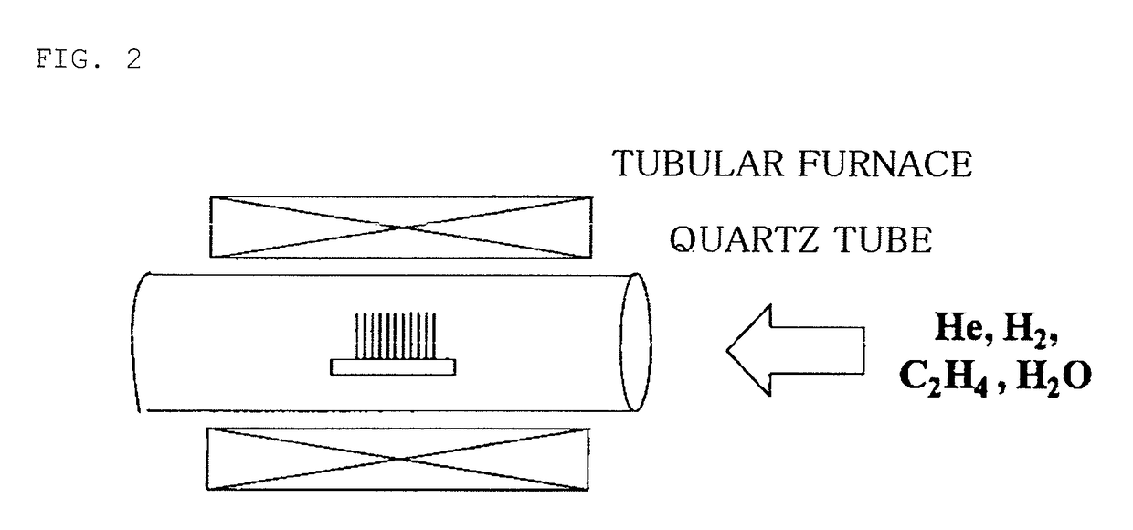
[0083]An Al thin film (thickness: 10 nm) was formed on a silicon wafer (manufactured by Silicon Technology Co., Ltd.) serving as a substrate with a sputtering device (RFS-200 manufactured by ULVAC Inc.). An Fe thin film (thickness: 0.35 nm) was deposited from the vapor on the Al thin film with the sputtering device (RFS-200 manufactured by ULVAC Inc.).

[0084]After that, the substrate was placed in a quartz tube of 30 mmφ, and a helium / hydrogen (90 / 50 sccm) mixed gas whose moisture was kept at 600 ppm was caused to flow through the quartz tube for 30 minutes to replace the inside of the quartz tube. Then, the inside of the quartz tube was increased in temperature to 765° C. through use of an electric tubular furnace and stabilized at 765° C. While the temperature was kept at 765° C., the inside of the quartz tube was filled with a helium / hydrogen / ethylene (85 / 50 / 5 sccm, moisture content: 600 ppm) mixed gas. The quartz tube was left to stand for 1 minute to grow carbon nanotubes on the...


PUM

PropertyMeasurementUnit
lengthaaaaaaaaaa
particle diameteraaaaaaaaaa

Abstract

A carbon nanotube aggregate according to one embodiment of the present invention includes a plurality of carbon nanotubes, in which: the carbon nanotubes each have a plurality of walls; a distribution width of a wall number distribution of the carbon nanotubes is 10 walls or more; a relative frequency of a mode of the wall number distribution is 25% or less; and a length of each of the carbon nanotubes is more than 10 μm. A carbon nanotube aggregate according to another embodiment of the present invention includes a plurality of carbon nanotubes, in which: the carbon nanotubes each have a plurality of walls; a mode of a wall number distribution of the carbon nanotubes is present at a wall number of 10 or less; a relative frequency of the mode is 30% or more; and a length of each of the carbon nanotubes is more than 10 μm.

Description

TECHNICAL FIELD[0001]The present invention relates to a carbon nanotube aggregate and a viscoelastic body using the carbon nanotube aggregate.BACKGROUND ART[0002]A viscoelastic body is useful as a material for a pressure-sensitive adhesive, and has been actively researched and developed in various industrial fields, by virtue of its excellent balance between elasticity and viscosity (see Patent Literature 1). Because of its low modulus, a pressure-sensitive adhesive formed of the viscoelastic body becomes wet to conform to an adherend, thereby expressing its pressure-sensitive adhesive strength.[0003]Hitherto, an acrylic resin, a rubber-based resin, a silicone-based resin, or the like has been generally used as the material for a pressure-sensitive adhesive.[0004]Meanwhile, a fibrous columnar structure having a fine diameter has been known to exhibit pressure-sensitive adhesive property. It has been elucidated that the structure follows surface unevenness of an adherend to express i...

Claims


Application Information

Patent Timeline
Patent Type & Authority Patents(United States)
IPC IPC(8): B07B13/04B82Y30/00B82Y40/00
CPCB07B13/04B82Y30/00B82Y40/00C01B32/162C01B2202/08C01B2202/34Y10S977/753Y10S977/962Y10T428/249924Y10T428/2918Y10S977/752C01B32/16C01B32/158C01B2202/00
Inventor MAENO, YOUHEI
Owner NITTO DENKO CORP
Why Eureka
Try Eureka