Method to improve the thermal properties of a resistance element embedded in an alumina deposit on a surface of a substrate and application of said method

a technology of alumina deposits and thermal properties, which is applied in the direction of machines/engines, mechanical equipment, chemical coatings, etc., can solve the problems of loss of electrical signals, reduced reliability of deformation measurements made using this gauge, and risk of substantial financial loss

Active Publication Date: 2017-10-31
SN DETUDE & DE CONSTR DE MOTEURS DAVIATION S N E C M A
View PDF9 Cites 0 Cited by
  • Summary
  • Abstract
  • Description
  • Claims
  • Application Information

AI Technical Summary

Benefits of technology

[0019]By densifying the surface alumina deposit, it is therefore possible to fill the porosity and the microcracks located in the surface portion of this deposit and, hence, to create a barrier able to protect the resistive element located in the underlying portion of the alumina deposit (called in this case the “deep portion”) against any oxidation, without however modifying the characteristics of the alumina deposit in this underlying portion.
[0020]The porosity and the microcracks present in the underlying portion of the alumina deposit can therefore be preserved, such that the ductility of the alumina (which enables the resistive element to fulfil its function as a measuring instrument when it is a strain gauge) in this portion may be maintained.

Problems solved by technology

It has been observed that, if a strain gauge is used to measure the deformations which may be undergone by a part at temperatures of over 950° C., the electrical and mechanical characteristics of this gauge are modified, causing a loss of the electrical signals which it is supposed to emit and, consequently, reduced reliability of the deformation measurements made using this gauge.
Reduced reliability of the measurements made on parts and, notably, on engine parts of an aircraft, may prejudice the certification campaign of this device and therefore lead to substantial delays in its development programme, with the risk of a substantial financial loss.

Method used


Image

  • Method to improve the thermal properties of a resistance element embedded in an alumina deposit on a surface of a substrate and application of said method
  • Method to improve the thermal properties of a resistance element embedded in an alumina deposit on a surface of a substrate and application of said method
  • Method to improve the thermal properties of a resistance element embedded in an alumina deposit on a surface of a substrate and application of said method

Examples


Embodiment Construction

[0017]This aim and others are met by the invention which proposes, firstly, a method for improving the heat resistance of a resistive element embedded in an alumina deposit covering a surface of a substrate, where the alumina deposit comprises a surface portion and a deep portion which is sandwiched between the surface portion and the surface of the substrate and in which the resistive element is located, which method is characterised in that it comprises a densification of the surface portion of the alumina deposit.

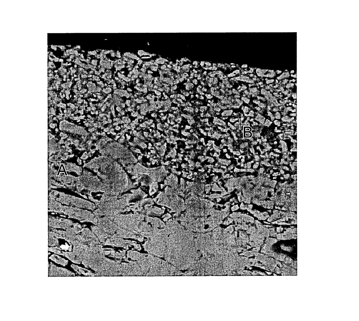
[0018]Indeed, in the course of their work, the Inventors observed that the modifications of the electrical and mechanical characteristics of a resistive element, of the strain gauge type, which are observed when this resistive element is embedded in an alumina deposit on a surface which is subjected to temperatures of over 950° C. results from an oxidation of the resistive element, and that this oxidation is due to the existence of interconnected pores and microcracks (w...


PUM

PropertyMeasurementUnit
temperature T1aaaaaaaaaa
temperature T2aaaaaaaaaa

Abstract

A method for improving the heat resistance of a resistive element embedded in an alumina deposit covering a surface of a substrate, in which the alumina deposit includes a surface portion and a deep portion which is sandwiched between the surface portion and the surface of the substrate and in which the resistive element is located, is provided. The method includes a densification of the surface portion of the alumina deposit.

Description

TECHNICAL FIELD[0001]The invention relates to a method enabling the heat resistance of a resistive element to be improved when this resistive element is embedded in an alumina deposit on a surface of a substrate.[0002]This method notably finds applications in all fields in which an evaluation of the deformation of mechanical parts, which are intended to be exposed to very high temperatures, i.e. typically over 950° C., by means of resistive elements of the strain gauge type, is required and, in particular, in the field of design of engine parts for aeronautics, such as turbine blades.[0003]The invention therefore also relates to a turbine blade comprising a surface covered with an alumina deposit in which at least one resistive element is embedded, the thermal properties of which have been improved by said method.[0004]Lastly, it relates to a turbine comprising such a blade, and also to a turbomachine comprising such a turbine.STATE OF THE PRIOR ART[0005]In the field of design of en...

Claims


Application Information

Patent Timeline
Patent Type & Authority Patents(United States)
IPC IPC(8): B05D3/02C04B35/10F01D21/00F01D5/28C23C18/12B32B18/00
CPCF01D21/003B32B18/00C04B35/10C23C18/127C23C18/1208C23C18/1283F01D5/288F05D2300/173C04B2235/3217C04B2235/447C04B2235/616C04B2237/343C04B2237/704F05D2230/90C04B41/5031F01D5/286
Inventor GISLARD, VANESSA AURELIERUELLE, MELANIE ALICE CAMILLE
Owner SN DETUDE & DE CONSTR DE MOTEURS DAVIATION S N E C M A
Why Eureka
Try Eureka