
Thermally stable high temperature pressure and acceleration optical interferometric sensors

a technology of optical interferometer and high temperature pressure, applied in the field of fiber optic pressure transducers, can solve the problems of thermal expansion mismatch, optical glass measurement error and/or cracking, cracking and fracturing at the adhesive joints, etc., and achieve the effect of reducing thermal expansion mismatch

Active Publication Date: 2017-11-07
KULITE SEMICON PRODS
View PDF36 Cites 1 Cited by
  • Summary
  • Abstract
  • Description
  • Claims
  • Application Information

AI Technical Summary

Benefits of technology

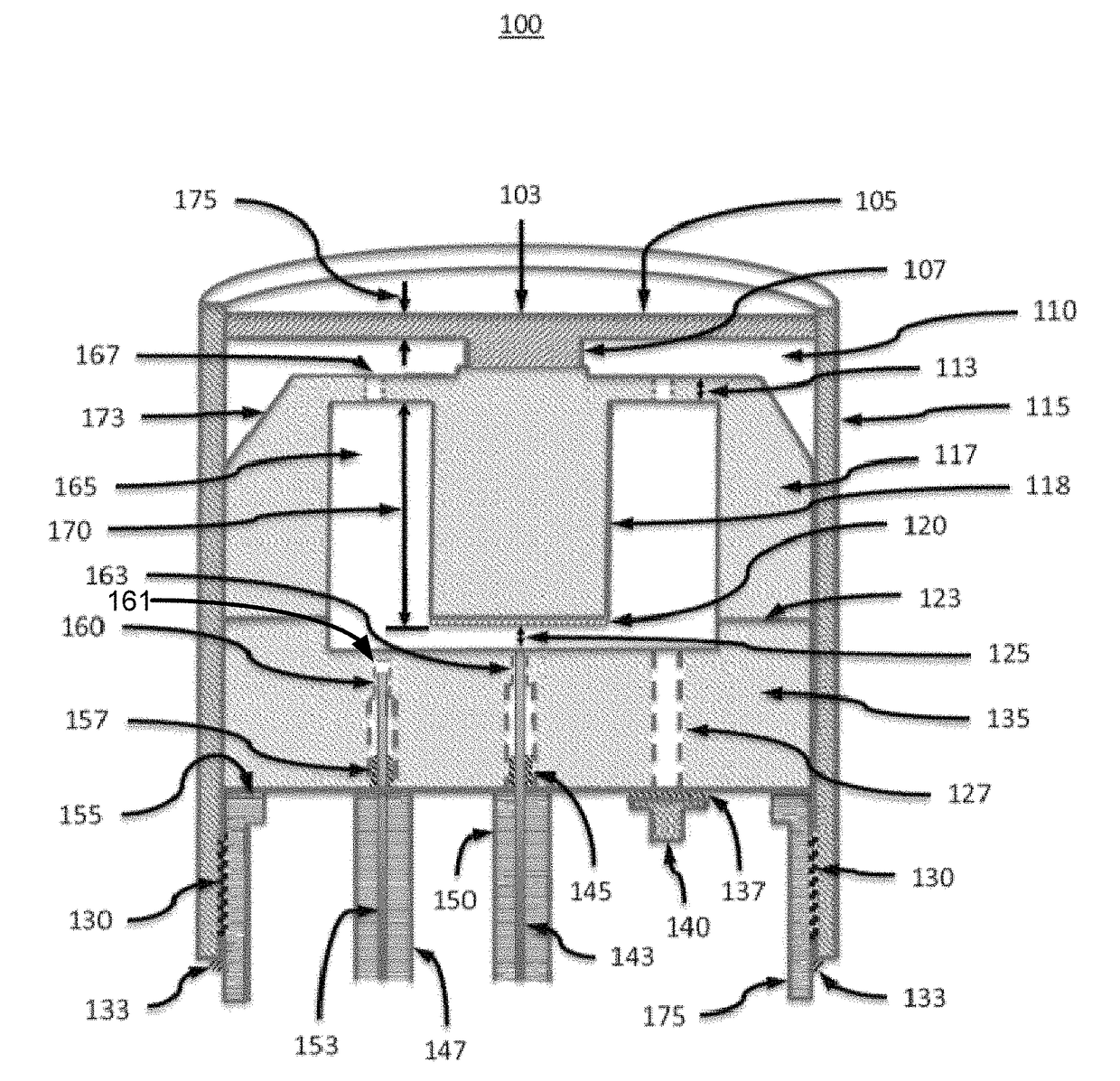
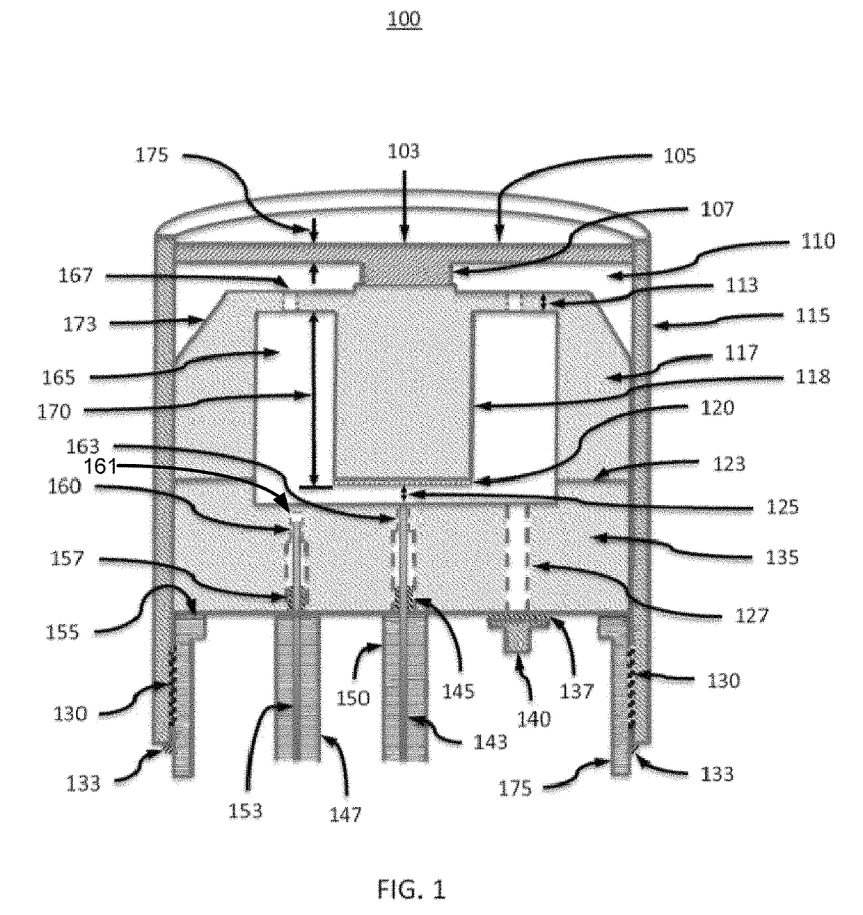
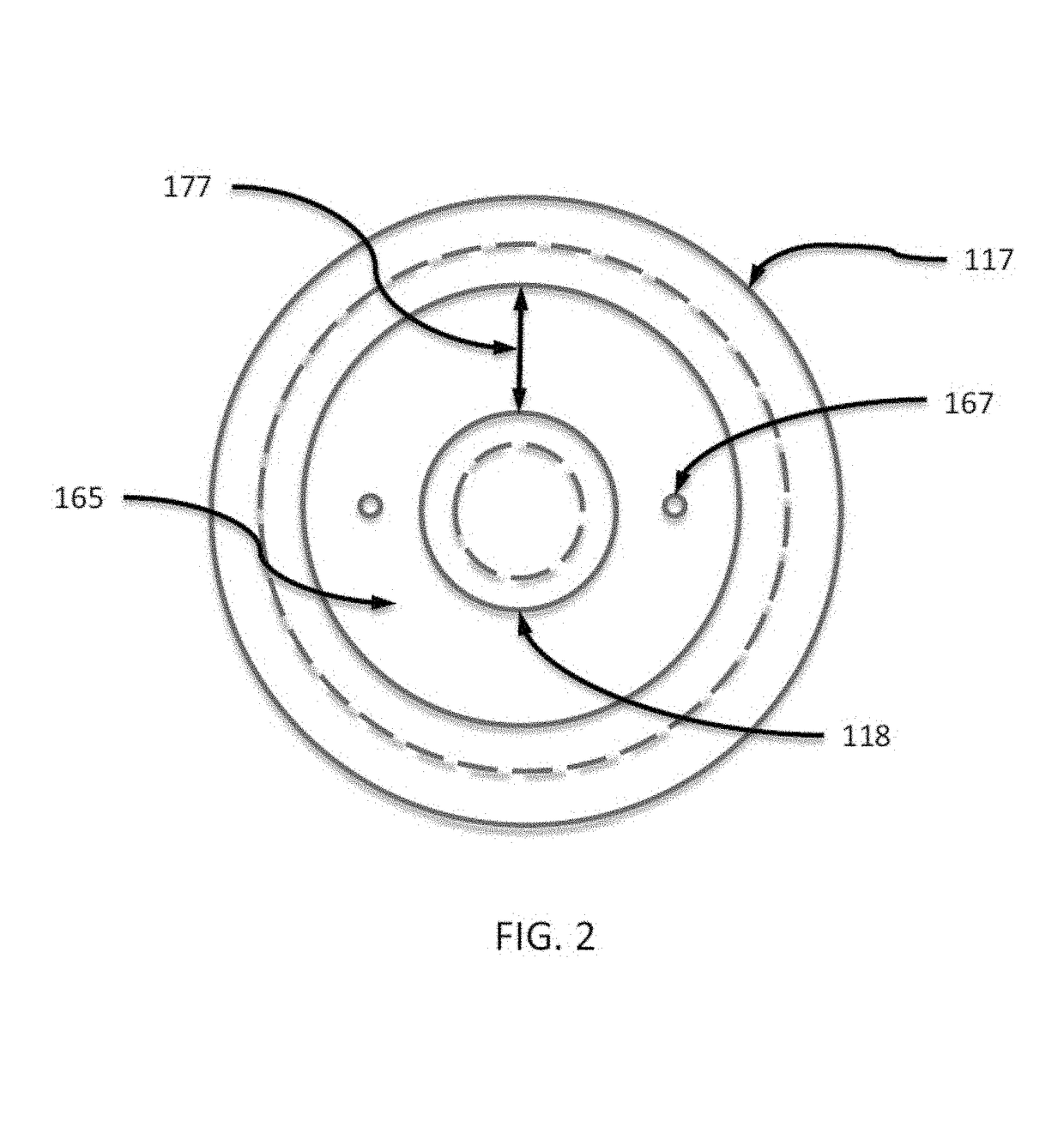
[0007]According to an example implementation of the disclosed technology, a sensor assembly is provided that includes a diaphragm configured to deflect responsive to an applied stimulus, a diaphragm support structure in communication with the diaphragm, and a sensing optical interferometer having a first optical cavity in communication with at least a portion of the diaphragm and the diaphragm support structure. The sensor assembly includes a sensing optical interferometer is configured to interact with received first light to produce a measurement light signal corresponding to the applied stimulus. The sensor assembly includes a reference optical interferometer having a second optical cavity in communication with the diaphragm support structure, the reference optical interferometer is configured to interact with received second light to produce a reference light signal. The sensor assembly can include a sensing optical fiber in communication with the sensing optical interferometer, and a reference optical fiber in communication with the reference optical interferometer. The sensor assembly includes a housing in communication with the diaphragm and the diaphragm support structure, and configured to reduce a thermal expansion mismatch in the sensor assembly.

Problems solved by technology

In a typical Fabry-Perot-style optical sensors, various problems can occur due to thermal expansion and contraction of sensor materials that have different coefficients of thermal expansion (CTE).
Mismatches in CTE can cause high thermal stress and strain between parts and cause deformation, which can result in measurement error and / or cracking of the optical glass in the extreme case.
Cracking and fracturing can occur at the adhesive joints between low CTE optical glasses and high CTE metallic supporting structures.
The adhesive joint, for example, can become a high strain region and can fracture due to the shear or tensile stress.

Method used


Image

  • Thermally stable high temperature pressure and acceleration optical interferometric sensors
  • Thermally stable high temperature pressure and acceleration optical interferometric sensors
  • Thermally stable high temperature pressure and acceleration optical interferometric sensors

Examples


Embodiment Construction

[0022]The following detailed description is merely illustrative in nature and is not intended to limit the present disclosure, or the application and uses of the present disclosure. Furthermore, there is no intention to be bound by any expressed or implied theory presented in the preceding field of use, background, or summary of the disclosure or the following detailed description. The disclosed technology includes various examples, embodiments and the like, which may be described herein in terms of functional or logical block elements.

[0023]Various techniques described herein may be used for a fluid-filled pressure sensor assembly capable of higher pressure environments. The various aspects described herein are presented as methods, devices (or apparatus), and systems that may include a number of components, elements, members, modules, nodes, peripherals, or the like. Further, these methods, devices, and systems may or may not include additional components, elements, members, modul...


PUM

PropertyMeasurementUnit
temperatureaaaaaaaaaa
melting pointaaaaaaaaaa
operating temperatureaaaaaaaaaa

Abstract

Certain example implementations of the disclosed technology include an optical-interferometer sensor assembly for measuring pressure or acceleration. The sensor assembly includes a diaphragm configured to deflect responsive to an applied stimulus, a diaphragm support structure in communication with the diaphragm, a sensing optical interferometer having a first optical cavity in communication with at least a portion of the diaphragm and the diaphragm support structure, and a reference optical interferometer having a second optical cavity in communication with the diaphragm support structure. The sensor assembly can include a sensing optical fiber in communication with the sensing optical interferometer and a reference optical fiber in communication with the reference optical interferometer. The sensor assembly can include a housing in communication with the diaphragm and the diaphragm support structure, and configured to reduce a thermal expansion mismatch in the sensor assembly.

Description

CROSS REFERENCE TO RELATED APPLICATIONS[0001]This application claims priority to U.S. Provisional Patent Application No. 62 / 101,314, filed 8 Jan. 2015, and entitled “Thermally Stable High Temperature Pressure and Acceleration Optical Interferometric Sensors,” the contents of which is hereby incorporated by reference in its entirety as if presented in full.[0002]This application is also related to U.S. Non-Provisional patent application Ser. No. 14 / 705,585, filed 5 May 2015, and entitled “Systems and Methods for Optical Measurements using Multiple Beam Interferometric Sensors,” the contents of which is hereby incorporated by reference in its entirety as if presented in full.TECHNICAL FIELD[0003]This disclosure generally relates to pressure sensors and more particularly to a fiber optic pressure transducer and method for making the sameBACKGROUND[0004]In a typical Fabry-Perot-style optical sensors, various problems can occur due to thermal expansion and contraction of sensor materials...

Claims


Application Information

Patent Timeline
Patent Type & Authority Patents(United States)
IPC IPC(8): G01B9/02G01P15/093G01L9/00G01L19/04
CPCG01L19/04G01P15/093G01L9/0079
Inventor SANZARI, MARTIN A.
Owner KULITE SEMICON PRODS
Learn More