Managing data placement based on flash drive wear level

a technology of managing data and flash drives, applied in the direction of memory adressing/allocation/relocation, instruments, input/output to record carriers, etc., can solve the problems of excessive disk arm movement, bus occupancy and availability, uneven load distribution across disks

Active Publication Date: 2017-11-07
EMC IP HLDG CO LLC
View PDF8 Cites 64 Cited by
  • Summary
  • Abstract
  • Description
  • Claims
  • Application Information

AI Technical Summary

Benefits of technology

[0010]A method is used in managing data in a data storage system. The method includes identifying a tiered storage pool wherein the storage pool includes multiple tiers having multiple storage units. A wear indicator for each of the multiple storage units is monitored. A first storage unit having a wear indicator greater than a second storage unit is identified. High activity data on the first storage unit is also identified. The identified high activity data is migrated from the first storage unit to the second storage unit.

Problems solved by technology

Examples of physical constraints include bus occupancy and availability, excessive disk arm movement, and uneven distribution of load across disks.
One factor that may limit the performance of a storage array is the performance of each individual storage component.
Different storage technologies, such as a flash memory device, may fail primarily due to wear out or usage, such as after performing a certain number of write cycles to store data on the flash memory device.
After performing the specified number of writes to the cell, that cell is expected to fail when attempting to subsequently write data thereto.
The foregoing is one example of a data storage technology and cause of wear out where the device may be expected to fail after a specified amount of usage.

Method used


Image

  • Managing data placement based on flash drive wear level
  • Managing data placement based on flash drive wear level
  • Managing data placement based on flash drive wear level

Examples


Embodiment Construction

)

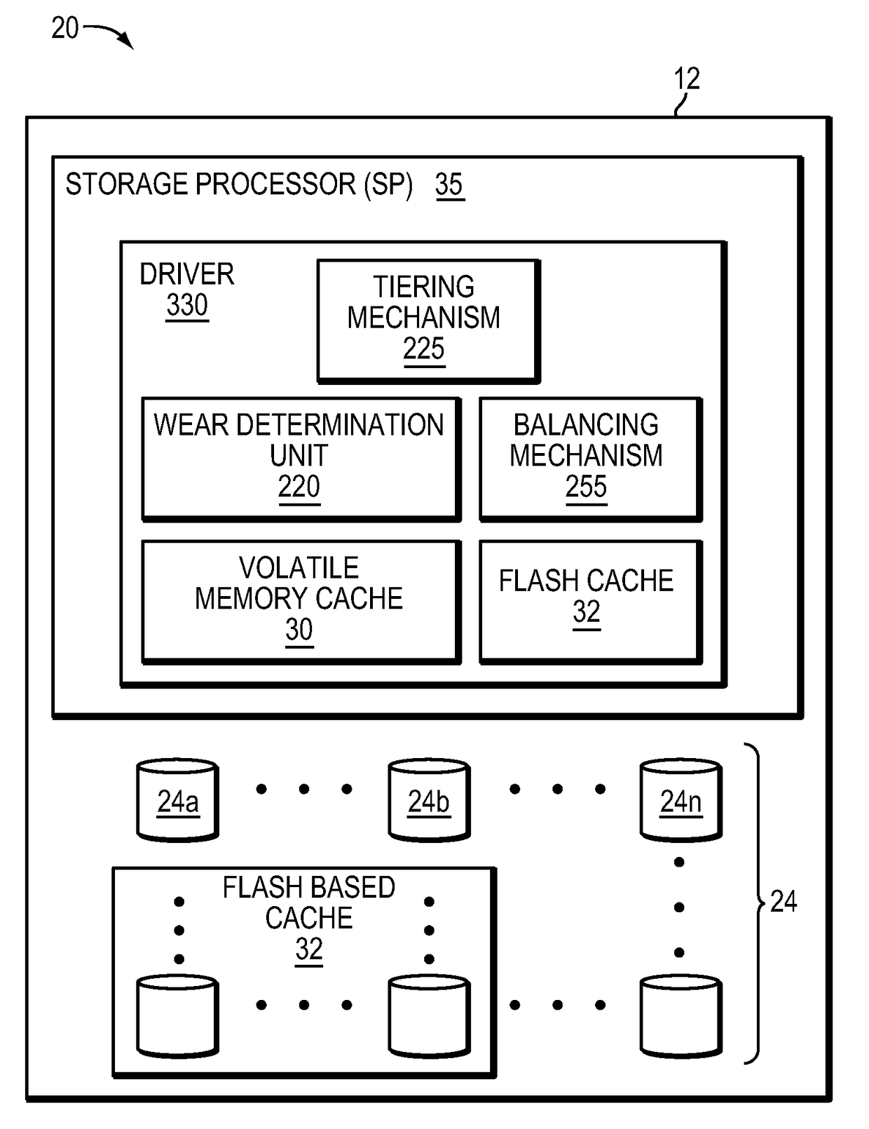
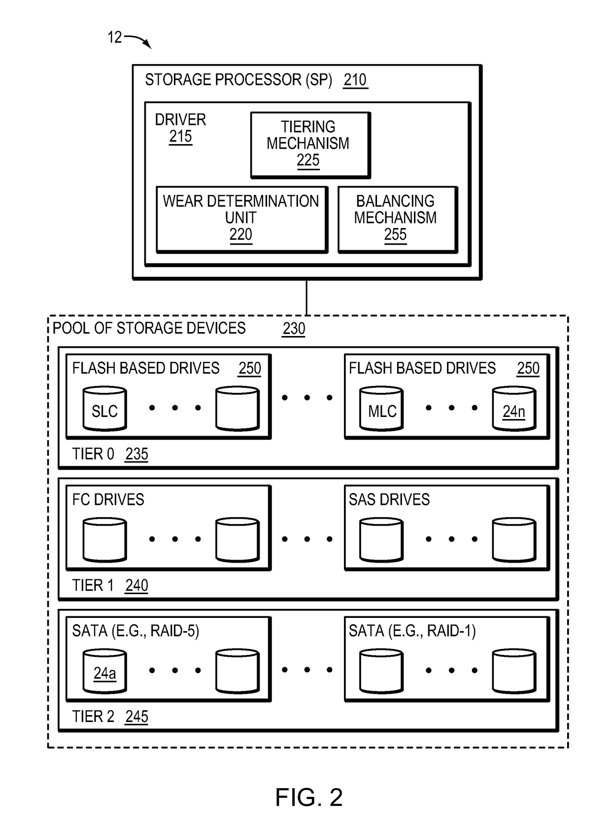
[0016]Flash drives are typically specified as having an expected lifetime (e.g., as measured in an amount of actual elapsed time such as a number of years, months, and / or days) based on a number of guaranteed write cycles and a rate or frequency at which the writes are performed. Thus, a flash drive may be expected to have a usage measured in calendar or wall clock elapsed time based on the amount of time it takes to perform the number of guaranteed write cycles. As discussed in more detail below herein, the techniques described herein may be used to help prolong the lifetime or expected lifetime of a group of flash drives associated with a tier in a storage pool that may be included in a data storage array by balancing high activity data across the group of flash drives. More generally, the techniques herein may be used to help improve the likelihood that any type of flash drive within a group of drives lasts for a specified amount of time (e.g., a required or specified lifetime) ...


PUM


Abstract

A method is used in managing data in a data storage system. A tiered storage pool is identified wherein the storage pool includes multiple tiers having multiple storage units. A wear indicator for each of the multiple storage units is monitored. A first storage unit having a wear indicator greater than a second storage unit is identified. High activity data on the first storage unit is also identified. The identified high activity data is migrated from the first storage unit to the second storage unit.

Description

BACKGROUNDTechnical Field[0001]This application relates to managing data placement based on flash drive wear level.Description of Related Art[0002]A traditional storage array (herein also referred to as a “disk storage array”, “disk array”, or simply “array”) is a collection of hard disk drives operating together logically as a unified storage device. Storage arrays are designed to store large quantities of data. Storage arrays typically include one or more storage array processors (SPs), for handling both requests for allocation and input / output (I / O) requests. An SP is the controller for and primary interface to the storage array.[0003]Storage arrays are typically used to provide storage space for one or more computer file systems, databases, applications, and the like. For this and other reasons, it is common for storage arrays to logically partition a set of disk drives into chunks of storage space, called logical units, or LUs. This enables a unified storage array to provide th...

Claims


Application Information

Patent Timeline
Patent Type & Authority Patents(United States)
IPC IPC(8): G06F12/02G06F3/06
CPCG06F3/0679G06F3/0616G06F3/0647G06F3/0685
Inventor CHEN, XIANGPINGDUPREY, DENNIS T.LINNELL, THOMAS E.TAO, QINKU, MARK K.
Owner EMC IP HLDG CO LLC
Why Eureka
Try Eureka