
Latch interface for a valve actuating device

Active Publication Date: 2017-11-21
EATON INTELLIGENT POWER LIMITED
View PDF196 Cites 17 Cited by
  • Summary
  • Abstract
  • Description
  • Claims
  • Application Information

AI Technical Summary

Benefits of technology

The patent for this patent modification is about a rocker assembly for an engine. It has a unique design that allows it to fit into engines with obstructions on the sides. The assembly includes an inner rocker structure and an outer structure that can rotate around an axle. A torsion spring helps to keep the inner structure in a position that is offset from the outer structure. This design allows for mode switching between low and high lift modes, while also reducing the mass and moments of inertia. The use of a diamond-like carbon coating has been shown to be robust and durable. Overall, the patent describes a way to improve the performance of rocker assemblies in engines.

Problems solved by technology

The latch seat has an indentation shaped to receive the latch pin and sized to compensate for at least a portion of the increase lash caused by increased manufacturing tolerances, and result in a predefined lash.

Method used


Image

  • Latch interface for a valve actuating device
  • Latch interface for a valve actuating device
  • Latch interface for a valve actuating device

Examples


second embodiment

[0250]In a second embodiment, illustrated in FIGS. 14C and 14D, the LVDT arrangement described above is modified by removing the second coil 898 in (FIG. 14A). When coil 898 is removed, the voltage induced in coil 897 will vary relative to the end position 874 of the core 873. In embodiments where the direction and timing of movement of the valve 872 is known, only one secondary coil 897 is necessary to measure magnitude of movement. As noted above, the core 873 portion of the valve can be located and fabricated using several methods. For example, a weld at the end position 874 can join nickel base non-core material and iron base core material, a physical reduction in diameter can be used to locate end position 874 to vary magnetic flux in a specific location, or a slug of iron-based material can be inserted and located at the end position 874.

[0251]It will be appreciated in light of the disclosure that the LVDT sensor components in one example can be located near the top of the val...

third embodiment

[0259]A third embodiment can position sensor 828 to directly evaluate the latch 200 position in the DVVL rocker arm assembly 100. The latch 200 and sensor 828 are engaged and fixed relative to each other when they are in the latched state (high lift mode), and move apart for unlatched (low-lift) operation.

[0260]Movement may also be detected using and inductive sensor. Sensor 877 may be a Hall-effect sensor, mounted in a way that allows measurement of the movement or lack of movement, for example the valve stem 112.

[0261]2.4.4 Pressure Characterization

[0262]Variable valve actuation (VVA) technologies are designed to change valve lift profiles during engine operation using switching devices, for example a DVVL switching rocker arm. Because latch status is an important input to the ECU that may enable it to perform various functions, such as regulating fuel / air mixture to increase gas mileage, reduce pollution, or to regulate idle and knocking, measuring devices or systems that confirm...


PUM

PropertyMeasurementUnit
Forceaaaaaaaaaa
Diameteraaaaaaaaaa
Hardnessaaaaaaaaaa

Abstract

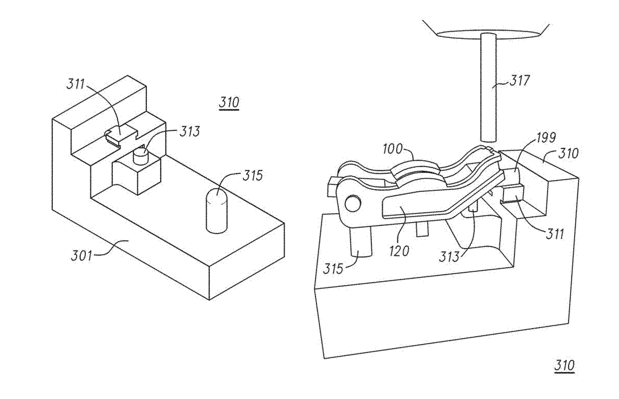
A novel latch seat for a switching rocker arm assembly used in variable valve actuation (VVA) systems for internal combustion engines. The seat is formed interactively in the assembled switching rocker arm using a novel fixture and press. The press interactively creates a curved dimple of the correct curvature, position and depth while measuring several lash dimensions. Since the latch seat is formed on the assembled rocker arm assembly, the latch seat depth is designed to account for the inaccuracies in the rocker arm assembly parts which create lash. Therefore all of the parts may be made with less precision since the latch seat is sized to compensate for the inaccuracies of all of the parts. The rocker arm assembly parts now may be manufactured to less stringent standards, but result in a rocker arm assembly with same accuracy of rocker arm assemblies manufactured to previous standards.

Description

CROSS REFERENCE TO RELATED APPLICATIONS[0001]This application is a continuation of U.S. Nonprovisional application Ser. No. 14 / 840,243, filed Aug. 31, 2015, entitled “Latch Interface for a Valve Actuating Device. U.S. Non-provisional application Ser. No. 14 / 840,243 is a continuation of International Application PCT / US2014 / 019870 (EATN-0213-WO) filed Mar. 3, 2014, entitled “Latch Interface for a Valve Actuating Device.”[0002]International Application PCT / US2014 / 019870 claims the benefit of: U.S. Provisional Applications 61 / 771,721 (EATN-0106-P01) entitled “Process to Form a Latch Interface for a Valve Actuating Device”; 61 / 771,716 (EATN-0105-P01) entitled “Latching Mechanism Interface for a Valve Actuating Device” both filed Mar. 1, 2013; 61 / 771,769 (EATN-0202-P01) filed Mar. 1, 2013, entitled “Discrete Variable Valve Lift Device and Methods.” International Application PCT / US2014 / 019870 is a continuation-in-part of each of the following applications: U.S. application Ser. No. 14 / 188,...

Claims


Application Information

Patent Timeline
IPC IPC(8): F01L1/18B21D39/00B21D53/84B23P19/02F01L13/00F01L1/22F01L1/24F01L1/053
CPCF01L1/22B21D53/84B23P19/02F01L1/18F01L1/185F01L1/2405F01L13/0005F01L13/0021F01L13/0036F01L13/0042B21D39/00Y10T29/53796F01L2001/0537F01L2001/186F01L2013/001F01L2101/00F01L2103/01F01L2800/11F01L2820/01F01L2820/043Y10T29/49297Y10T29/53F01L2303/01F01L2301/00Y10T29/49295Y10T29/49247Y10T29/49764Y10T29/49771
Inventor SPOOR, ANTHONY L.SHEREN, JAMES R.
Owner EATON INTELLIGENT POWER LIMITED
Learn More