Apparatus and method for treating multiple tumors in patients with metastatic disease by electric fields

a tumor and electric field technology, applied in the field of tumor and cancer cell treatment, can solve the problems of tingling on the patient's skin, single small insulated electrodes cannot meet these requirements, and the small elements used individually cannot draw the required energy

Active Publication Date: 2017-12-05
LIFEBRIDGE INNOVATIONS PBC
View PDF17 Cites 11 Cited by
  • Summary
  • Abstract
  • Description
  • Claims
  • Application Information

AI Technical Summary

Benefits of technology

[0035]An advantage of the present invention is that each array element in the inventive device can be redirected to either power sub-array A or B and to any array combination desired and to any frequency desired.
[0036]Another advantage of the present invention is that it allows for a universal system that can adapt to body composition and the spread of metastatic disease.

Problems solved by technology

Small elements used individually cannot draw the required energy.
Single small insulated electrodes cannot meet these requirements.
.), the resulting concentration of that much energy in a small area generally causes tingling on the patient's skin making treatment regimen unbearable.3. If small elements were used individually to produce TTF's, their physical size and shape would create inefficiencies when treating massive areas like cancer spread throughout the pleura membranes.
While large insolated electrodes 20, shown in FIG. 2, produce adequate fields, they have many disadvantages such as the inability to expand when a patient's skin stretches during bending or sitting.
This creates serious drawbacks when treating patients with metastatic disease.
Additionally, there are also small tumors located on the liver.
However, in the above scenario cross firing may not be possible because of the significant difference in size between the lung and liver insulated electrodes, 40A and 40B.
The significant limitation of the prior art is that each sub-element 12 of either array 40 or 42 is solely dedicated to its respective home insulated electrode array and to its home sub-array A or B array.
This limitation in the prior art leads to treatment compromises, putting the patient at risk by failing to treat new tumors as the primary disease.
TTF's vary in intensity throughout their shape, which can cause significant areas of a field to be below the effective strength.
As shown by region 46B, it is possible for tumors to be covered by a field without actually having any beneficial effect because the intensity is not sufficient enough to prevent cell division.
In addition, the extreme variance of tissue types and even air pockets within the body can create pockets where field formation is not possible if treatment is attempted from limited directions.
However, prior art treatment with dedicated array elements is compromising the treatment of the patient in this example.
Prior art treatment with dedicated array elements does not have enough versatility to adequately address multiple disease locations.
Also, the distance to the back liver and lung arrays are too far from the front peritoneal cavity to create an effective field.
Such short comings in the prior art can lead to a lack of tumor resolution, unnecessary pain and suffering in the patient, or even death.
The prior art is inefficient in that new custom dedicated arrays need to be constantly designed and physically built to address changes in patients with metastatic disease.
TTF treatment in the prior art fails the patient, as shown in FIGS. 4-6 and 8, and the patient will likely return to heavy chemotherapy, which can lead to days if not weeks of hospitalization and eventual death.
This however is inefficient when treating metastatic disease because the treatment areas continually change as the cancer spreads.
Some patients, desiring the resolution of their disease, may have a tendency to endure warm spots that are actually current leaks.
These leaks can cause blistering if not addressed quickly.
However, TTF arrays are expensive and in some cases can be worn for months at a time to save money.
The prior art systems lack a current monitoring system.
Array migration and overall warmth of the insulated electrodes can be an issue during TTF treatment.
When full body TTF arrays are worn during sleep and during other long periods of time it is a challenge to keep them from migrating to less optimal positions.
For example, tossing and turning during sleep can exasperate this problem.
In addition, warmth from the elements can cause sweating in some cases, which further enables slipping of the arrays as body movement occurs.
These methods are not as successful when used on full-body arrays.

Method used


Image

  • Apparatus and method for treating multiple tumors in patients with metastatic disease by electric fields
  • Apparatus and method for treating multiple tumors in patients with metastatic disease by electric fields
  • Apparatus and method for treating multiple tumors in patients with metastatic disease by electric fields

Examples


second embodiment

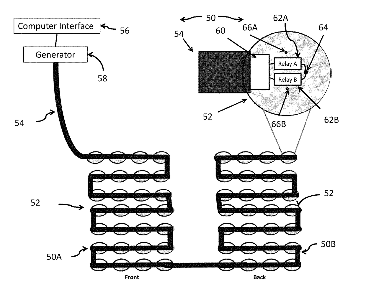
[0070]Now, additionally referring to FIG. 10, there is shown the present invention, an insulated electrode array 70 formed by sub-arrays 70A (front) and 70B (back). In this embodiment the communication wire is not used or is removed from the multilayer flex circuit 54 and each element 52 now includes a communication interface 72 with the integrated circuit 60. A signal is sent down the A and B lead wires of the multilayer flex circuit 54 at a different frequency than the TTF to direct the desired commands to each element 52. Also, the field generator 58 includes a command generator 74 for signaling the integrated circuit 60.

third embodiment

[0071]Referring now to FIG. 11, there is shown the present invention, an insulated electrode array 80 being formed by sub-arrays 80A (front) and 80B (back). In this embodiment, each individual element 52 includes a flexible wireless antenna 82 and a wireless communication interface 84 that enables the receiving of commands from a wireless signal generator 86 within the TTF field generator 58.

[0072]Referring now to FIG. 12, there is shown a fourth embodiment in the form of an insulated electrode array 90, a front sub-array 90A and a back sub-array 90B. In this embodiment, each integrated circuit 60 and relay pair 62A, 62B corresponding to a thin array element 92 is positioned in the same case 94 as the TTF generator 96. Thereby, the TTF generator 96 has a built-in dynamic reassignment. All the wires from the field generator 96 are run through the multilayer flex circuit 54, or any other suitable carrier, to each thin array element 92. Each thin array element 92 has its own power and ...

fifth embodiment

[0073]Referring now to FIG. 13, there is shown a fifth embodiment in the form of an insulated electrode array 100, pairing a front sub-array 100A and a back sub-array 100B. In this particular embodiment, the integrated circuit 60 is replaced by a small microprocessor 102. This embodiment allows pre-programmed firing states (array configurations and firing sequences) to be preloaded on each array element 52. This allows for broadcast communication to all array elements 52 simultaneously for faster switching. Each firing state is given a single or double digit ID. This firing ID code (or state ID) is appropriately broadcast to all array elements 52 at once. One message is sent to accomplish the firing state verses potentially hundreds using an integrated circuit alone.


PUM


Abstract

An insulated electrode system for delivering a plurality of tumor treating electromagnetic fields including an array of electrode elements for proximate location on a body of a patient. Each electrode element of the array having an insulation layer. Each electrode element being independently electrically accessible and configured to be dynamically assigned to emanate an electromagnetic field relative to at least one other of said electrode elements.

Description

CROSS REFERENCE TO RELATED APPLICATIONS[0001]This is a non-provisional application based upon U.S. provisional patent application Ser. No. 62 / 028,996, entitled “APPARATUS AND METHOD FOR TREATING MULTIPLE TUMORS IN PATIENTS WITH ADVANCED METASTATIC DISEASE BY ELECTRIC FIELDS”, filed Jul. 25, 2014, which is incorporated herein by reference.BACKGROUND OF THE INVENTION[0002]1. Field of the Invention[0003]The present invention relates to tumor and cancer cell treatment and more specifically to treatments involving the application of electromagnetic fields.[0004]2. Description of the Related Art[0005]Alternating Electric Fields, also referred to as Tumor Treating Fields (TTF's), can be employed as a type of cancer treatment therapy by using low-intensity electromagnetic fields. These low-intensity fields rapidly change direction, thousands of times per second. Since the TTF's are electric fields, they do not cause muscle twitching or severe adverse side effects on other electrically activ...

Claims


Application Information

Patent Timeline
Patent Type & Authority Patents(United States)
IPC IPC(8): A61N1/32A61N1/04A61N1/372A61N1/40
CPCA61N1/32A61N1/40A61N1/37217A61N1/0476A61N1/36002
Inventor TRAVERS, PETER F.WATKINS, KENVANDERMEY, TIMOTHY
Owner LIFEBRIDGE INNOVATIONS PBC
Why Eureka
Try Eureka