
Electrical power generation system using renewable energy

a renewable energy and electric power generation technology, applied in the direction of transmission systems, motors, photovoltaics, etc., can solve the problems of increasing the cost of electrical power supply for such electrically powered devices, increasing the cost of electrical power supply cables and the like, and requiring electrical power, so as to increase the speed of the turbine, increase the electrical power generated, and increase the air velocity

Inactive Publication Date: 2017-12-05
KING FAHD UNIVERSITY OF PETROLEUM AND MINERALS
View PDF20 Cites 6 Cited by
  • Summary
  • Abstract
  • Description
  • Claims
  • Application Information

AI Technical Summary

Benefits of technology

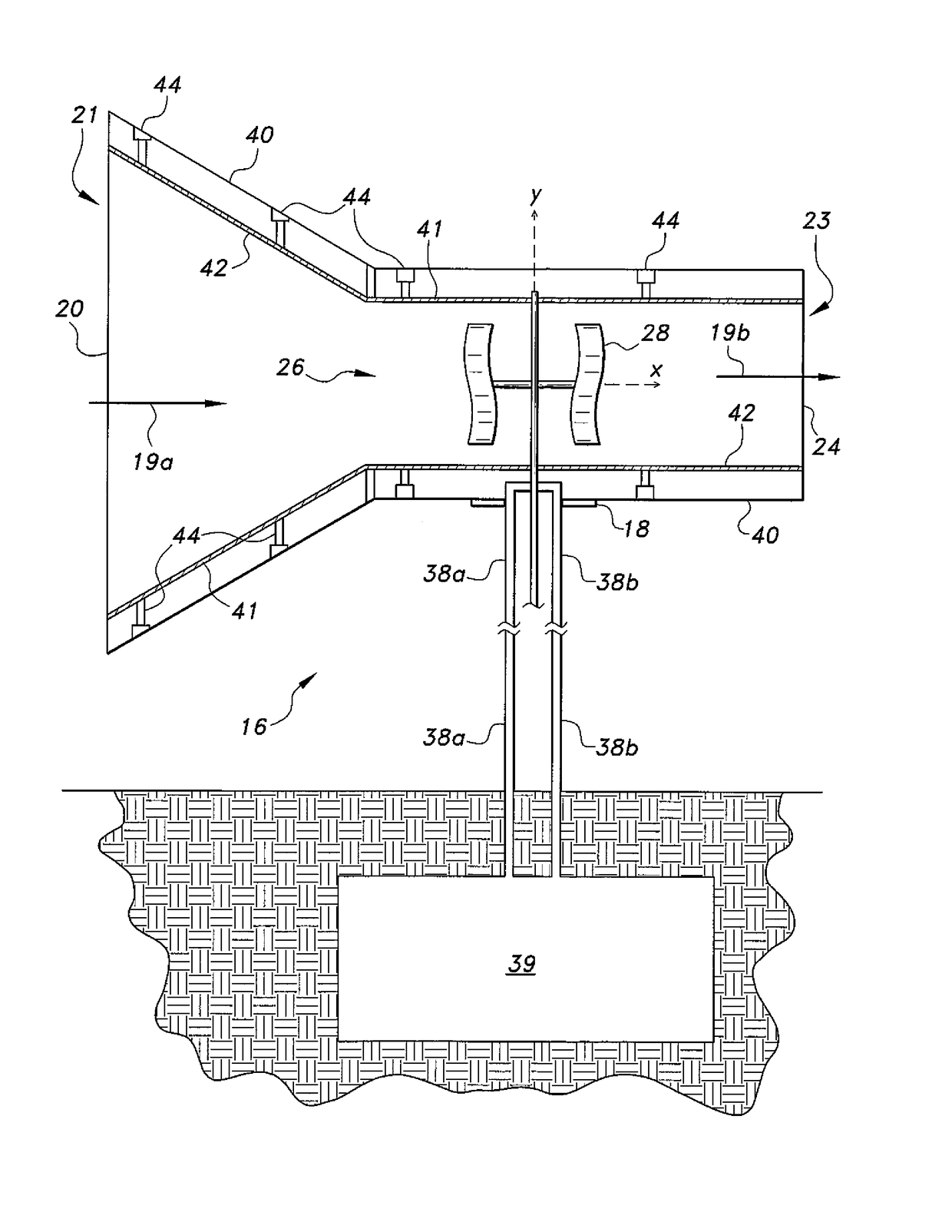
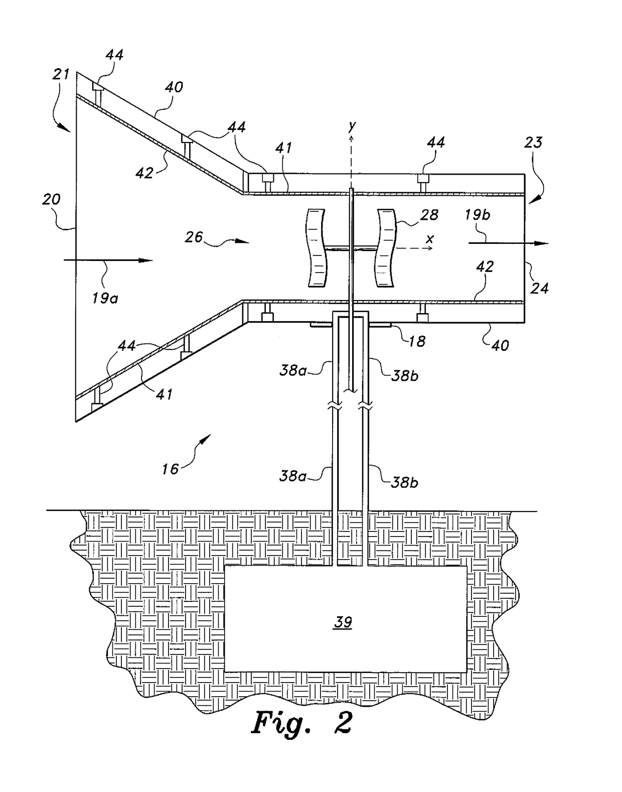
[0012]Heat may be provided to the venturi from a subterranean geothermal source. Heating the venturi can result in an increase in air velocity through the venturi throat due to the expansion of the air therein as it is heated, and the heated air can increase the speed of the turbine as can increase the electrical power generated. Such heat can also serve to reduce or substantially preclude the chance of ice formation in and around the venturi and, thus, can assist in providing operation in freezing conditions.

Problems solved by technology

However, such devices typically require electrical power.
The basic installation of an electric street light or emergency call box is generally not difficult or expensive, but the provision of electrical power for such devices can be quite costly and time consuming as trenches are dug for buried electrical cables or poles are placed for overhead electrical wiring.
Thus, the installation of electrical power cables and the like for such electrically powered devices can often cost considerably more than the electrical devices themselves.

Method used


Image

  • Electrical power generation system using renewable energy
  • Electrical power generation system using renewable energy
  • Electrical power generation system using renewable energy

Examples


Embodiment Construction

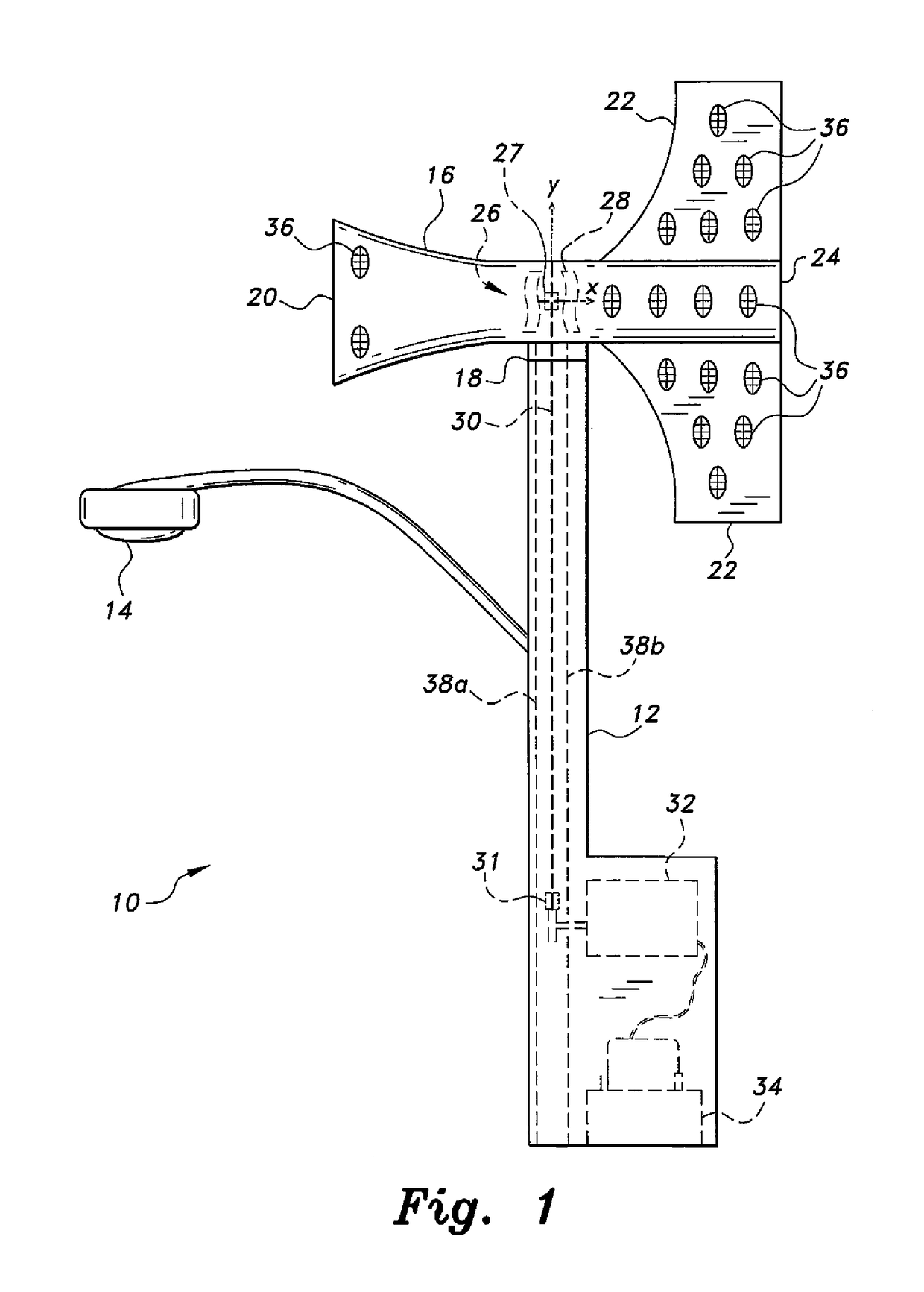
[0018]Embodiments of an electrical power generation system using renewable energy can provide electrical power for an independent or remotely located device, such as a street light, traffic information sign, emergency call box, lighting for a campground, and / or other similar installations, such as where the delivery of electrical power from a centralized power station can be impractical or unavailable. FIG. 1 provides a schematic side elevation view of an embodiment of an exemplary installation of the electrical power generation system 10, illustrating its basic components. The electrical power generation system 10 is adapted for installation on a pole 12 supporting a street light 14 or other electrical device or appliance, for example. A venturi 16 is mounted atop the pole 12 on a pivot or swivel mount 18, enabling the venturi 16 to swivel atop the pole 12, such as about a vertical axis Y, in accordance with changes in wind direction, such that an inlet 20 of the venturi 16 can be ...


PUM


Abstract

The electrical power generation system using renewable energy is particularly adapted to provide electrical power to an independent or remotely situated electrical device such as a street light, emergency call box, or illuminated road sign. The system includes a pivotally mounted venturi with vanes assuring that the venturi is oriented into the prevailing wind. A vertical axis wind turbine is installed in the venturi throat, and drives a shaft extending through the column upon which the venturi is installed to a generator at the base of the column. The venturi and vanes may include photovoltaic cells thereon for further electrical power. The venturi may be heated from a geothermal source, and may include a variable diameter internal wall to adjust the cross-sectional area of the throat of the venturi. The use of functionally graded materials and other phase change materials may also improve the performance of the device.

Description

REFERENCE TO RELATED APPLICATION[0001]This application is a continuation-in-part of U.S. patent application Ser. No. 13 / 974,010 filed on Aug. 22, 2013.BACKGROUND OF THE INVENTION[0002]1. Field of the Invention[0003]The present invention relates generally to the generation and production of electrical power, and particularly to an electrical power generation system using renewable energy including wind, solar, and / or geothermal energy sources.[0004]2. Description of the Related Art[0005]The development of various electrical appliances and devices has led to their widespread installation and use in virtually all developed areas of the world. Electric lighting for street lights and the like is nearly universal in urban and suburban areas throughout the world, and provision for other electrically powered devices (e.g., emergency call boxes, etc.) is also well known.[0006]However, such devices typically require electrical power. The basic installation of an electric street light or emerg...

Claims


Application Information

Patent Timeline
Patent Type & Authority Patents(United States)
IPC IPC(8): H02J1/00H02S10/12F03D9/00H02J4/00H02J3/00F03D3/04F03D3/00
CPCF03D3/0427F03D3/005F03D3/0418F03D9/007H02J4/00H02S10/12Y10T307/658F05B2220/708F05B2240/12F05B2240/133Y02E10/74Y02E10/50F03D9/25F03D9/34
Inventor AL-GARNI, AHMED Z.AVES, MOHAMMED
Owner KING FAHD UNIVERSITY OF PETROLEUM AND MINERALS
Learn More