Single-step interferometric radius-of-curvature measurements utilizing short-coherence sources

a technology of interferometry and radius of curvature, applied in the field of interferometry, can solve the problems of many faulty components that must be discarded, and achieve the effect of reducing the size of the hardwar

Active Publication Date: 2018-01-02
ONTO INNOVATION INC
View PDF8 Cites 8 Cited by
  • Summary
  • Abstract
  • Description
  • Claims
  • Application Information

AI Technical Summary

Problems solved by technology

In view of the foregoing, one of the challenges with interferometric measurements of the radius of curvature of a test article, especially in high throughput environments where the precision of the ROC is measured for production tolerance purposes, is that it requires two measurements; one in the cateye configuration and one in the confocal configuration.
As a result, radius of curvature measurements are typically done by random sampling off-line and, by the time an inaccuracy is detected in the production line, many faulty components are produced that must be discarded.

Method used


Image

  • Single-step interferometric radius-of-curvature measurements utilizing short-coherence sources
  • Single-step interferometric radius-of-curvature measurements utilizing short-coherence sources
  • Single-step interferometric radius-of-curvature measurements utilizing short-coherence sources

Examples


Embodiment Construction

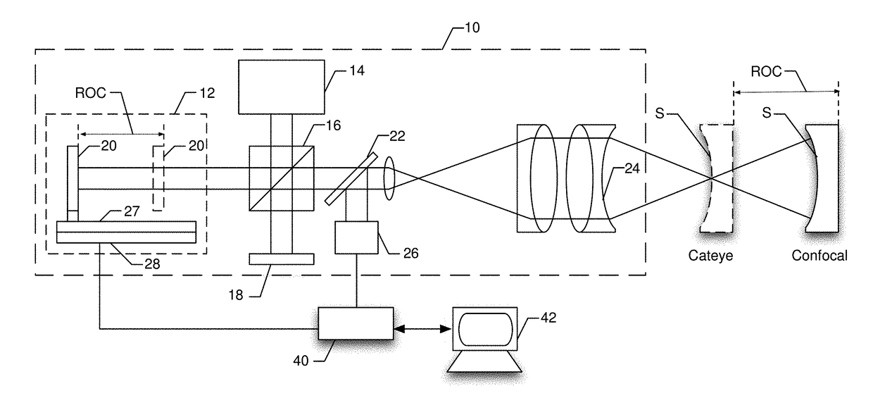
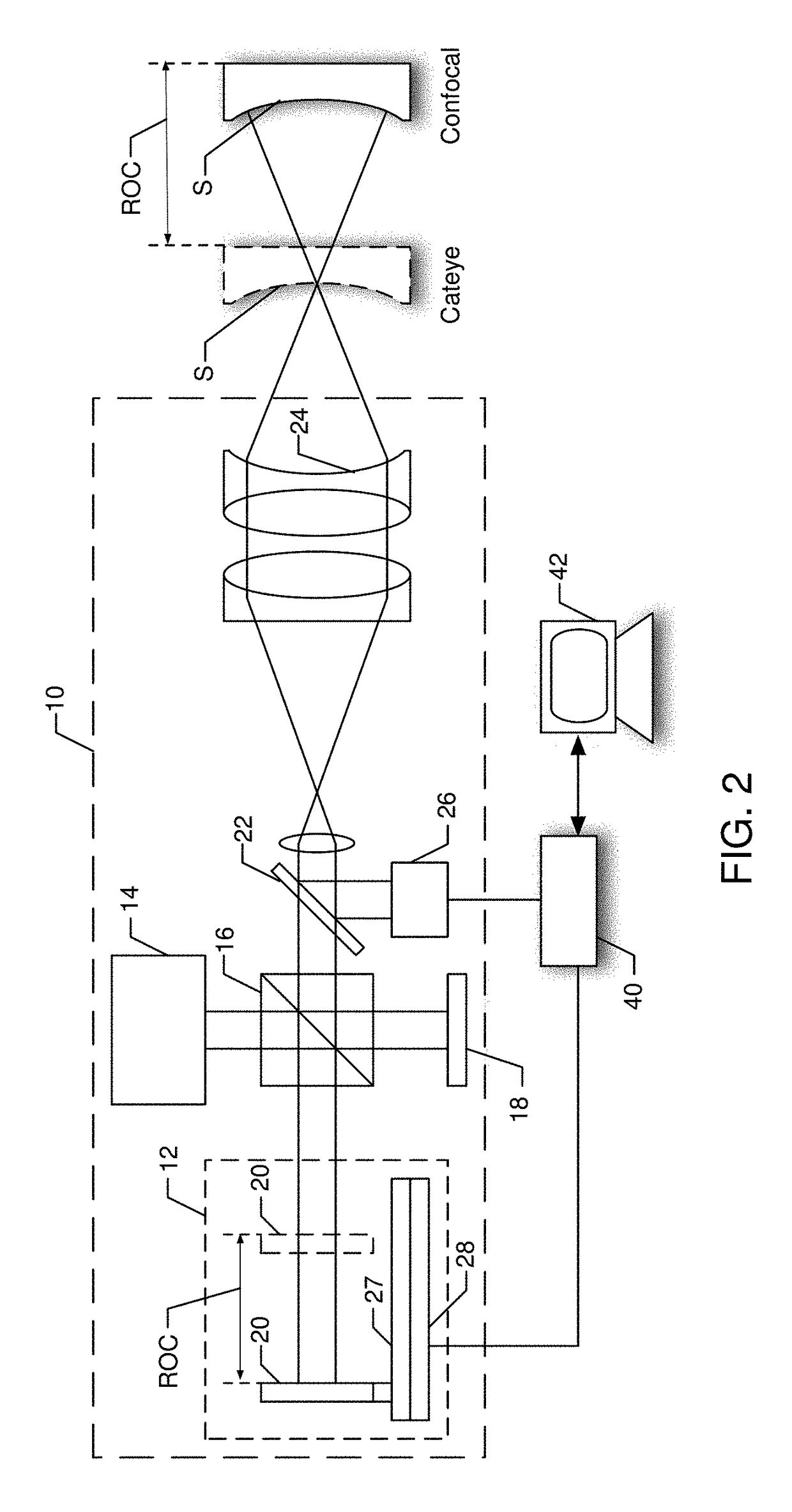
[0017]For the purposes of this specification of the invention, as described and claimed, “short-coherence” of a light source refers to light that has a full-width-half-max coherence length of 1 millimeter or less. The term “orthogonal polarizer” is used to describe any optical device that produces an output of two orthogonally polarized beams. Such beams are preferably, but not necessarily, achromatic. For instance, without limitation, cycloidal diffractive waveplates, birefringent prism pairs such as Wollaston, or interferometers like Fizeau or Twyman-Green with a polarizing beam-splitter coupled to quarter-wave plates, are hereby defined as orthogonal polarizers when configured to produce such output. The terms “dynamic interferometry” and “dynamic interferometer” are defined and used to include any interferometric method and corresponding apparatus where at least three phase-shifted interferograms can be produced simultaneously from two orthogonally polarized beams. The term “dyn...


PUM


Abstract

An interferometer includes a short-coherence source and an internal path-matching assembly contained within its housing. Because path matching occurs within the housing of the interferometer, it is removed from external environmental factors that affect measurements. Therefore, a single cateye measurement of an exemplary surface can be performed in advance and stored as a calibration for subsequent radius-of-curvature measurements. In one embodiment, a path-matching stage is incorporated into a dynamic interferometer where orthogonally polarized test and reference beams are fed to a dynamic imaging system. In another embodiment, orthogonal linearly polarized test and reference beams are injected into a remote dynamic interferometer by means of one single-mode polarization-maintaining optical fiber.

Description

RELATED APPLICATIONS[0001]This application is based on and claims the priority of U.S. Provisional Application Ser. No. 62 / 270,492, filed Dec. 21, 2015, and U.S. Provisional Application Ser. No. 62 / 270,500, filed Dec. 21, 2015, both hereby incorporated by reference.BACKGROUND OF THE INVENTIONField of the Invention[0002]The invention relates generally to interferometry. In particular, it relates to a method for measuring the radius of curvature of a lens utilizing a short-coherence source in a single-step procedure.Description of the Related Art[0003]Typically, when using an interferometer to measure the radius of curvature (ROC) of a sample, two measurements are taken with the test article placed at different positions along the optical axis. These positions are chosen such that the returning beam reflects back at the same angle as the incident beam producing an interference pattern at the camera that is substantially a single fringe, also known as a “null” fringe. The two locations...

Claims


Application Information

Patent Timeline
Patent Type & Authority Patents(United States)
IPC IPC(8): G01B11/24G01B11/255G01B9/02
CPCG01B11/255G01B9/02049G01B9/02065G01B9/02081G01B9/0209G01B2290/15G01B2290/70G01M11/005
Inventor NORTH MORRIS, MICHAELMILLERD, JAMES
Owner ONTO INNOVATION INC
Why Eureka
Try Eureka