
Method and apparatus for fracture reduction during internal fixation of distal radius fractures

Active Publication Date: 2018-01-09
JOHN M AGEE & KAREN K AGEE TRUSTEES OF THE JOHN M AGEE TRUST
View PDF9 Cites 5 Cited by
  • Summary
  • Abstract
  • Description
  • Claims
  • Application Information

AI Technical Summary

Benefits of technology

The patent describes a new method and apparatus for reducing and stabilizing fractures of the distal radius using a volar plate. The method involves using a pivot pin that is installed through the fracture and the extensor retinaculum, allowing for alignment and stabilization of the fracture fragments. The process involves applying forces to the fracture fragments and using the pivot pin to restore length, appositional alignment, palmar tilt, and ulnar inclination. The method has several advantages over previous techniques, including minimizing radiation exposure to the surgeon's hands, optimal fracture reduction, and reduced surgical time.

Problems solved by technology

The fall produces a sudden impact of the body weight on the heel of the hand, which results in a dorsally displaced fracture of the radius just proximal to the wrist joint with or without an associated wrist joint injury.
However, these fixation plates do not provide either the initial alignment or stabilization of the fracture fragments that are required during surgery for installation of a fixation plate.
The process of manipulating the fracture followed by obtaining multiple fluoroscopic images results in two disadvantages for the surgeon.
First, stabilizing the fracture reduction can be time consuming and requires either the use of both of the surgeon's hands or an assistant.
Consequently, the surgeon may be unable to simultaneously attend to other issues that may require use of his hands.
Second, because the fracture reduction is achieved only when the surgeon is holding the patient's wrist and hand, the surgeon is exposed to radiation from the fluoroscopy each time it is used to image the status of the fracture reduction.

Method used


Image

  • Method and apparatus for fracture reduction during internal fixation of distal radius fractures
  • Method and apparatus for fracture reduction during internal fixation of distal radius fractures
  • Method and apparatus for fracture reduction during internal fixation of distal radius fractures

Examples


Embodiment Construction

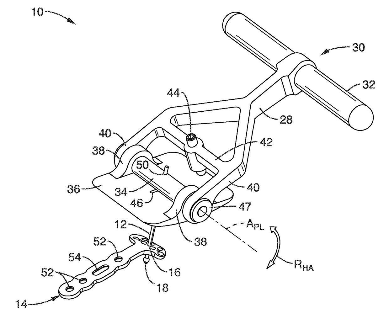
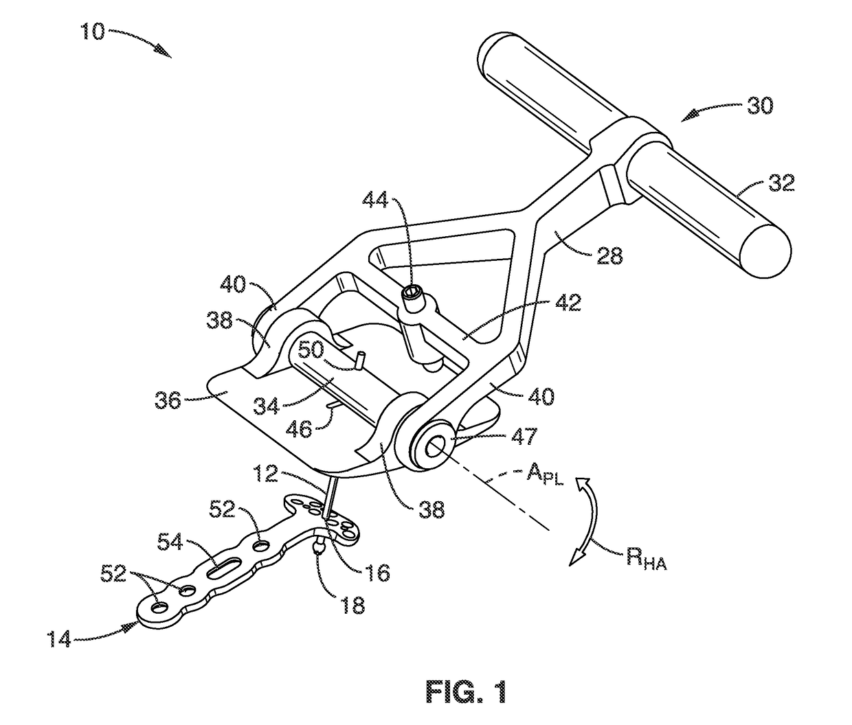
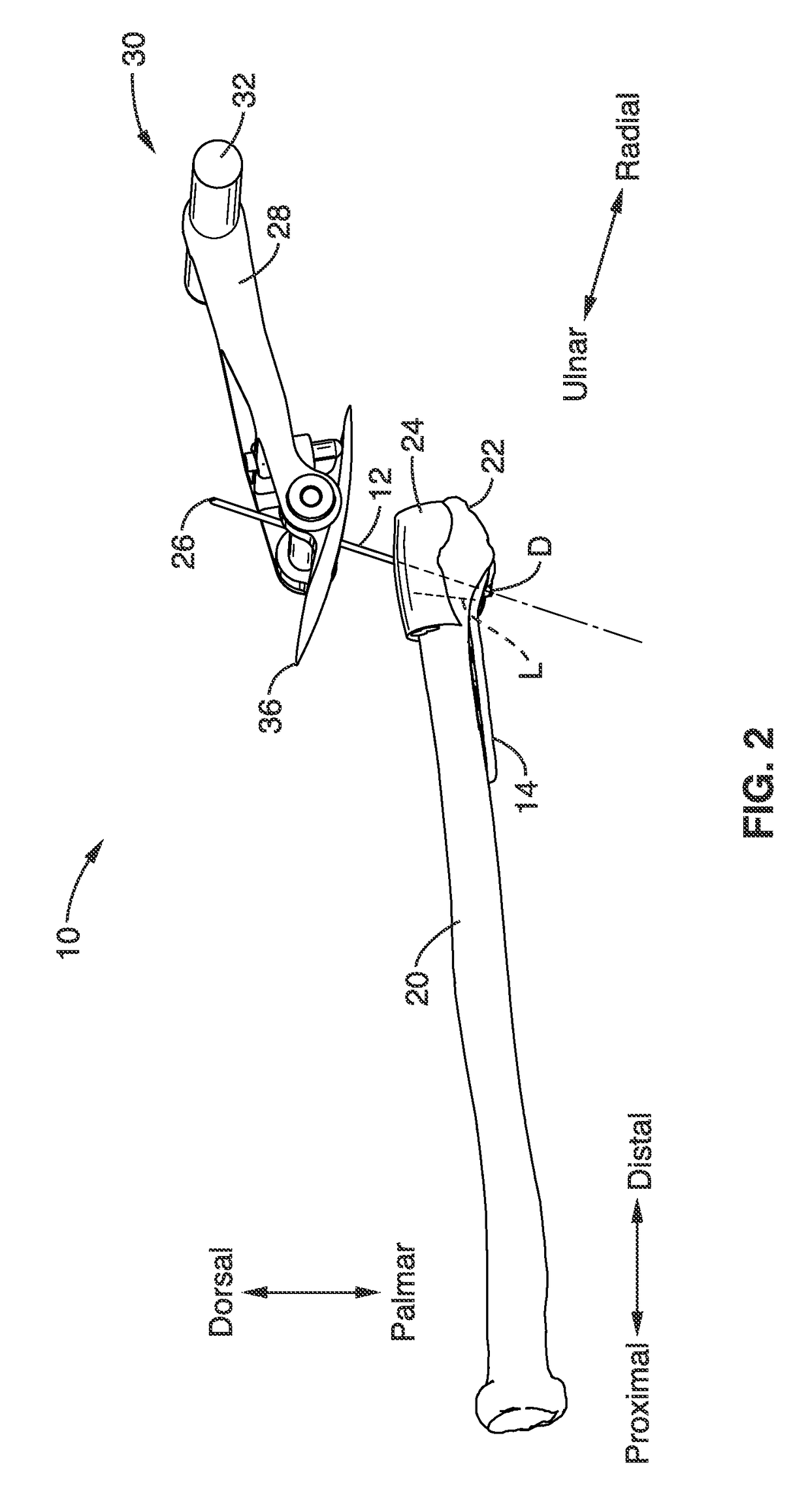
[0026]FIG. 1 and FIG. 2 show a first embodiment of a fracture reduction apparatus 10 according to the disclosure, for reducing and stabilizing a fracture at the distal end of a radius 20 prior to and during surgical installation of a volar plate 14. For purposes of clarity, only the radius 20 and extensor retinaculum 24 are shown in FIG. 2 and FIG. 4. All other anatomy, including other bones and tissues (e.g. ligaments, tendons, musculature, skin, etc.), are excluded from these illustrations.

[0027]In the embodiment shown in FIG. 1 and FIG. 2, the fracture reduction apparatus 10 comprises a pivot pin 12 (shown in further detail in FIG. 5) for creating an attachment point at a distal location D at a point distal to a distal fracture line L, and that inserts through a hole 16 in the volar plate 14.

[0028]Apparatus 10 further comprises a handle assembly 30 comprising a pivot link 34 for slidably coupling a T-handle 32 and a dorsal platform 36 with the pivot pin 12 (both prior to and duri...


PUM


Abstract

An apparatus for treating a fracture of the distal radius of a patient, having a pivot pin configured to engage the radius at an attachment point distal to the fracture, and a handle assembly configured to engage the pivot pin dorsal to the patient's hand is presented. The pivot pin is configured to insert through and fixedly engage at least a portion of the distal fracture bone fragment associated with the radius. The handle assembly, once coupled to the pivot pin, provides adjustment of the position of the distal fracture bone fragment.

Description

CROSS-REFERENCE TO RELATED APPLICATIONS[0001]This application claims priority to, and the benefit of, U.S. provisional patent application Ser. No. 61 / 881,787 filed on Sep. 24, 2013, incorporated herein by reference in its entirety.STATEMENT REGARDING FEDERALLY SPONSORED RESEARCH OR DEVELOPMENT[0002]Not ApplicableINCORPORATION-BY-REFERENCE OF COMPUTER PROGRAM APPENDIX[0003]Not ApplicableNOTICE OF MATERIAL SUBJECT TO COPYRIGHT PROTECTION[0004]A portion of the material in this patent document is subject to copyright protection under the copyright laws of the United States and of other countries. The owner of the copyright rights has no objection to the facsimile reproduction by anyone of the patent document or the patent disclosure, as it appears in the United States Patent and Trademark Office publicly available file or records, but otherwise reserves all copyright rights whatsoever. The copyright owner does not hereby waive any of its rights to have this patent document maintained in...

Claims


Application Information

Patent Timeline
IPC IPC(8): A61B17/56A61B17/84A61B17/88A61B17/68A61B17/80
CPCA61B17/846A61B17/8872A61B17/8897A61B2017/564A61B2017/681A61B17/808A61B17/8061A61B17/8866
Inventor AGEE, JOHN M.WOODHOUSE, JEFFREYKING, FRANCIS C.
Owner JOHN M AGEE & KAREN K AGEE TRUSTEES OF THE JOHN M AGEE TRUST
Learn More