
Temporary rain water collection assembly for use on a roof of a building

a technology for building roofs and rain water collection, applied in roof drainage, sewage draining, turf growing, etc., can solve problems such as localized flooding, wastewater and pollution, and increase in the amount of impermeable surfaces, and achieve the effect of promoting the free movement of air

Active Publication Date: 2018-01-30
PERMALOC CORP
View PDF7 Cites 4 Cited by
  • Summary
  • Abstract
  • Description
  • Claims
  • Application Information

AI Technical Summary

Benefits of technology

The system effectively collects and manages rainwater, reducing storm water runoff, providing evaporative cooling, and protecting roof membranes, while being scalable and cost-effective, thus alleviating flooding risks and enhancing urban aesthetics.

Problems solved by technology

As these developed urban areas began to increase in population and expand into larger sub-urban areas, the amount of impermeable surfaces increased, creating a significant increase in storm water runoff.
The large impermeable areas generate enormous amounts of water runoff during moderate to heavy rainfall events, far exceeding the design capacities of the existing grey conveyance systems, resulting in localized flooding, wastewater and pollution issues.
Many cities have built combined sewer and storm water systems that lack the capacity to handle the increased storm water.
In these circumstances, the sewer systems quite often have to release untreated sewer water into the waterways during moderate storm events.
Although vegetated roof systems have proven to be successful on a modest scale, they are limited in their application potential.
Not every roof can support the weight of a vegetated system.
Further vegetated systems are limited in that an urban rooftop is a very challenging environment to grow plants.
There are many challenges, such as drought, climate extremes, high winds, pollution, poor maintenance and a limited plant palate.

Method used


Image

  • Temporary rain water collection assembly for use on a roof of a building
  • Temporary rain water collection assembly for use on a roof of a building
  • Temporary rain water collection assembly for use on a roof of a building

Examples


Embodiment Construction

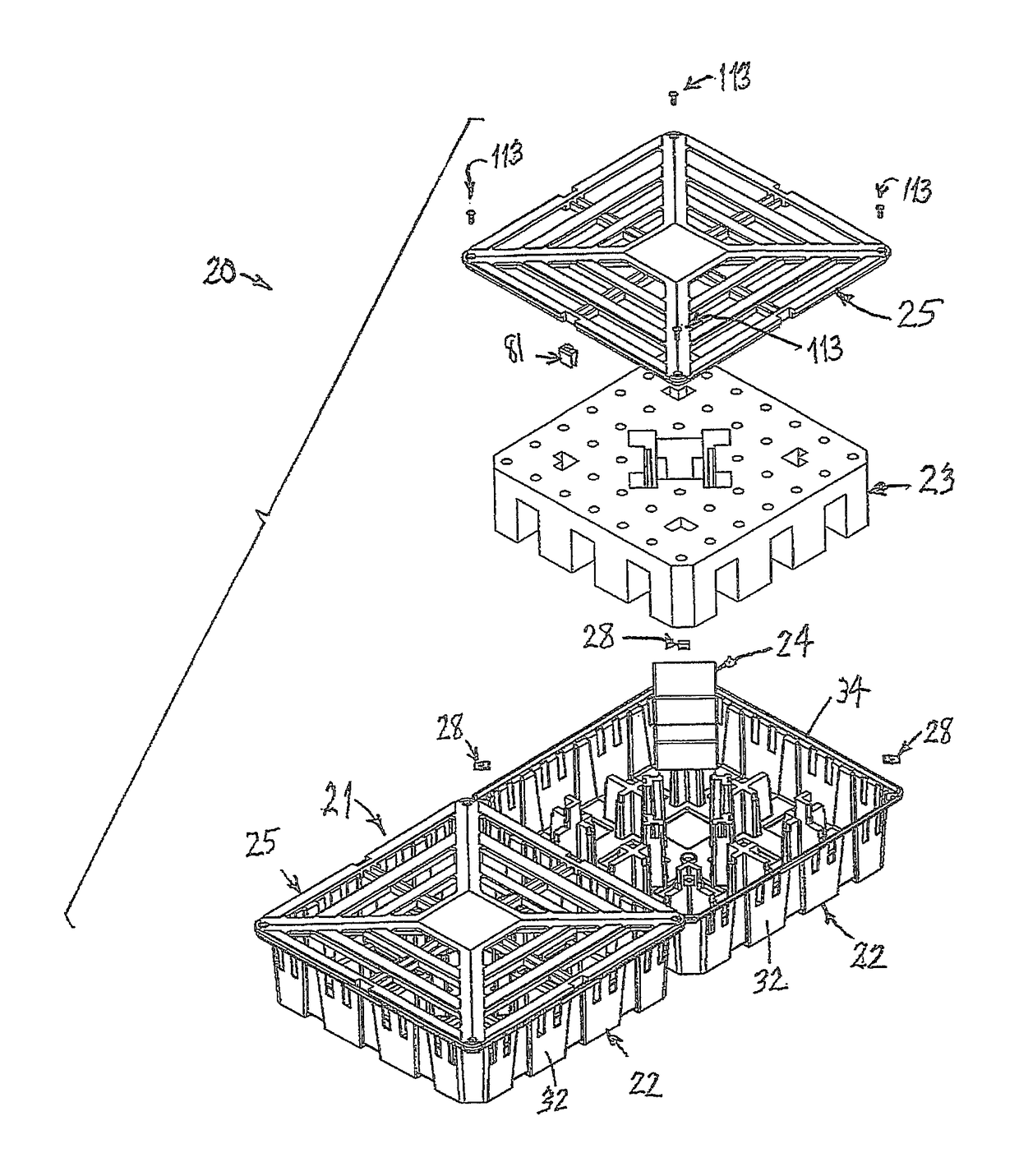
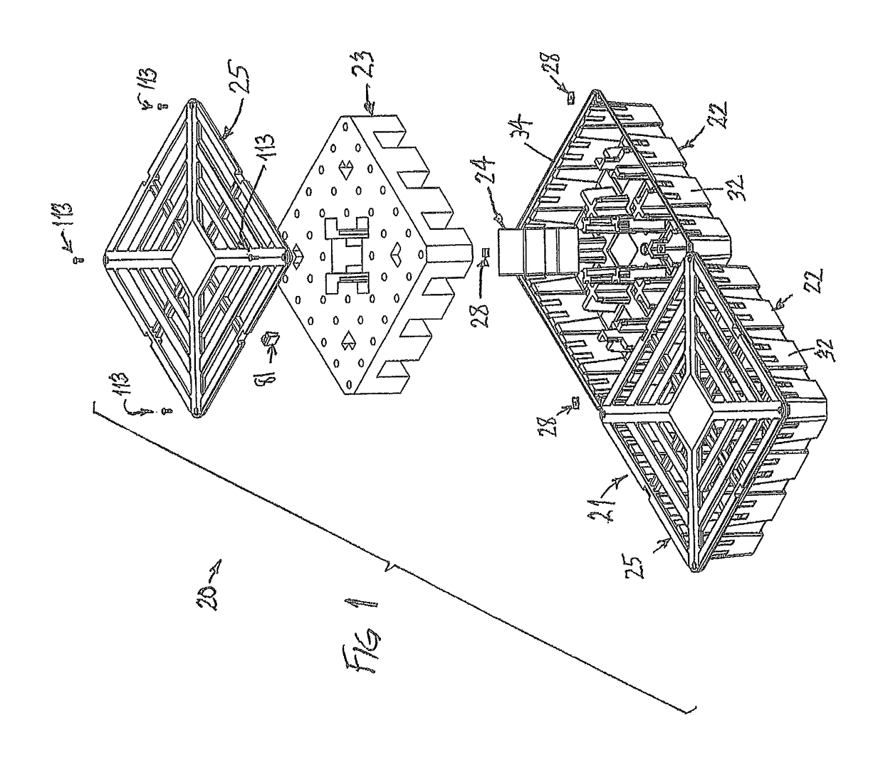
[0034]FIG. 1 illustrated a rain water collection system 20 and includes a plurality of individual tray assemblies 21 that are interconnected to one another as will be explained in more detail below. Each tray assembly 21 has a container 22, an absorbing layer 23, ballast assemblage 24 and a cover plate assembly 25.

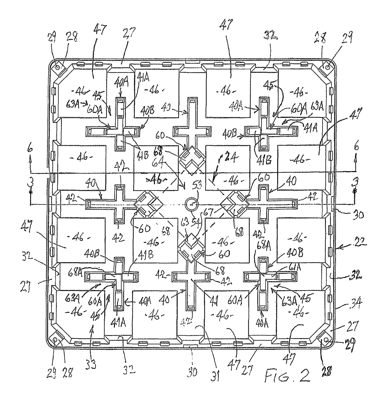
[0035]The container 22 (FIGS. 2 and 3) is formed from a suitable thermoplastic resin based material, such as ABS, Polyethylene, Polypropylene. metal or wood and includes a bottom wall 31 and a plurality of upstanding sidewalls 32 that are integral with the bottom wall 31 and with each other. In this particular embodiment, the container is rectangular or square as shown in the top view of FIG. 2 and includes four upstanding sidewalls 32 to define an interior region 33 of the container 22. Each of the sidewalls 32 are inclined to the vertical and terminate at an upper horizontally flat surface 27 that is oriented in a plane that is parallel to a plane containing the floor of...


PUM


Abstract

A rain water collection system for a blue roof system that includes a tray assembly comprising a container, a water absorbing layer located in said interior region of the container, ballast members and a cover plate. The water absorbing layer is supported on a first set of support surfaces to locate the water absorbing layer above the bottom wall of the container to provide a water collecting space into which will flow excess water that exceeds the water absorbing capacity of the water absorbing layer. The sidewalls of the container have openings therethrough to facilitate the passage of over flow water from the container and the introduction of air therethrough into the interior region. The upstanding columns have openings to facilitate the passage of air therethrough into the interior region of the container.

Description

CROSS REFERENCE TO RELATED APPLICATION[0001]This claims the benefit of U.S. Provisional Application No. 62 / 066,620, filed Oct. 21, 2014, which is hereby incorporated by reference in its entirety.FIELD OF THE INVENTION[0002]This invention relates to a rain water collection system for a blue roof system.BACKGROUND OF THE INVENTION[0003]Urban storm water is rain that falls over urban and suburban areas, or any place with a large percent cover of impervious surfaces such as roads, parking lots, and roofs. The management of this water is of increasing critical interest for developers, designers, and municipalities that are facing increasing ecological and political pressure to maintain pre-development site hydrology. This has been recognized in Lenhart US published patent application no. 2014 / 0026480 A1, published on Jan. 30, 2014.[0004]During the 20th century, many of North America's major urban areas were developed with a large portion of the land area being covered by impervious surfa...

Claims


Application Information

Patent Timeline
Patent Type & Authority Patents(United States)
IPC IPC(8): E04D13/04E04D11/00E03B3/03E03F1/00
CPCE04D13/0404A01G1/007E03F1/005E04D11/002E03B3/03Y02B80/32Y02A20/108Y02A30/254A01G9/033Y02A20/00
Inventor ZWIER, DANIEL G.ANDERSON, ROBERT D.KOOPS, PHILIP L.HERDEGEN, DENNIS C.
Owner PERMALOC CORP
Learn More