Method and apparatus for generating a multi-level pseudo-random test signal

a multi-level pseudo-random test and generator technology, applied in the direction of digital transmission, instruments, wireless communication, etc., can solve the problems of inability to provide multi-level signaling, difficult to test multi-level i/os of devices, and symbols generated by assigning subsets of bits to multi-level symbols no longer uniformly distributed

Inactive Publication Date: 2018-01-30
IBM CORP
View PDF11 Cites 0 Cited by
  • Summary
  • Abstract
  • Description
  • Claims
  • Application Information

AI Technical Summary

Benefits of technology

[0022]The above method may allow for the generation of multi-level pseudo-random symbol sequences for testing a transmission of a multilevel signal so that the received multi-level signal can be evaluated by a conventional binary PRBS checker. Therefore, the multi-level PRBS signal to be generated should comply with conventional PRBS checkers for binary signals and also provide the required characteristics of binary signals. The required characteristics of the test signal received in the PRBS checker are a specific frequency of zero crossings and a uniform distribution of symbols. This may allow for the simplification of the system testing if no multi-level checking device is available.
[0023]One idea of the embodiments of the invention is to extend a conventional binary PRBS generator with a symbol mapping unit which provides a positive and a negative valued symbol to the respective binary state of the binary signal provided by a conventional binary PRBS generator. The positive and negative symbols are respectively generated or provided on a per-bit basis of the binary PRBS signal so that the zero-crossings of the original binary PRBS pattern is maintained and hence a binary PRBS checker can be used for the verification of a received test signal, which has been transmitted over a transmission path to be tested. Furthermore, a uniform distribution also for short test pattern length can be obtained. Yet furthermore still, the frequency of the zero crossings of the original binary PRBS pattern is not affected.

Problems solved by technology

The testing of multi-level I / Os of devices, however, is difficult, since conventional testing equipment is typically merely providing binary test signals.
Such PRBS generators are designed for NRZ (non-return to zero) or 2-PAM pattern and cannot provide multi-level signaling due to the concept of generation.
Furthermore, for short test pattern lengths, the symbol generated by assigning the subsets of bits to a multi-level symbol are no longer uniformly distributed.
Furthermore, in feedback loop timing limited systems, the pattern generator needs to be operated at a much faster clock rate and hence clock boundary crossing and random-logic-macro (RLM) timing become an issue.

Method used


Image

  • Method and apparatus for generating a multi-level pseudo-random test signal
  • Method and apparatus for generating a multi-level pseudo-random test signal
  • Method and apparatus for generating a multi-level pseudo-random test signal

Examples


Embodiment Construction

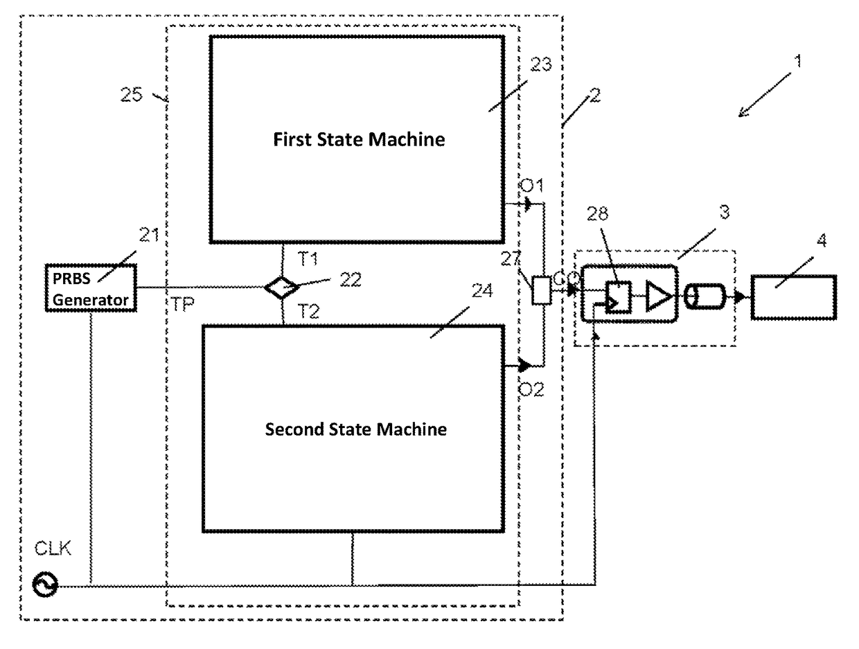
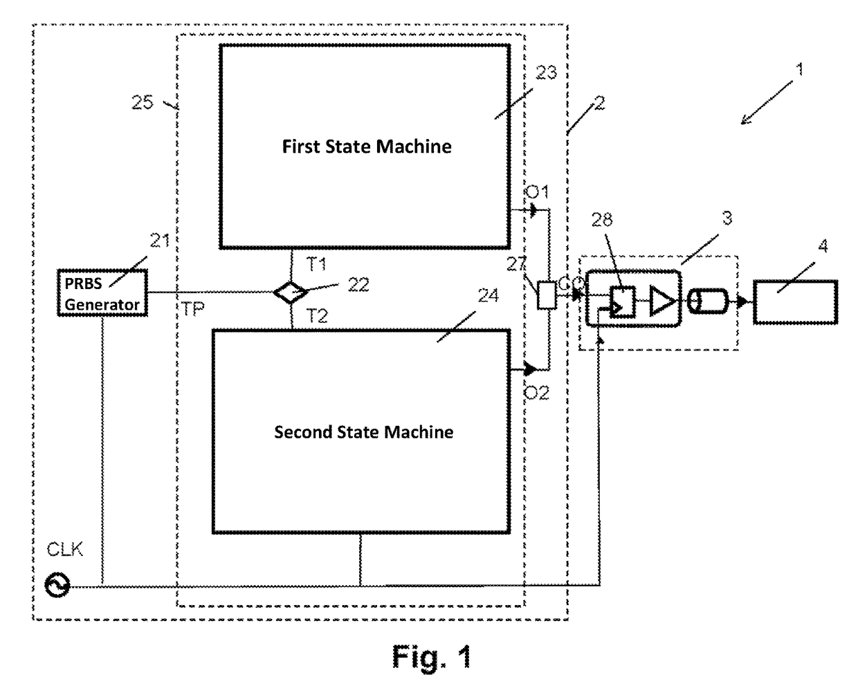
[0036]The process of generating a multilevel pseudo random test signal is described now in conjunction with the test system of FIG. 1 and the method as illustrated by the flow chart of FIG. 3.

[0037]Referring to FIG. 1, a test system 1 is illustrated having a test symbol generator 2, a transmission channel 3 and a checking unit 4 to evaluate the transmitted test signal.

[0038]The test signal generator 2 comprises a standard binary NRZ (non-return to zero) PRBS (pseudo-random bit signal) generator 21 which outputs a serial sequence of a binary test pattern TP. The PRBS generator 21 is clocked by a clock signal CLK having a base frequency f0.

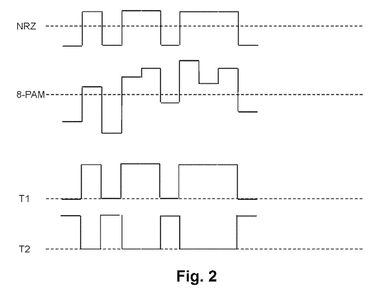
[0039]The pseudo-random bit sequence TP generated by the PRBS generator 21 is supplied to a bit tester 22 of a mapping unit 25. The bit tester 22 provides a first trigger signal T1 and a second trigger signal T2 for each clock cycle. The first trigger signal T1 corresponds to a sequence of signal pulses which may, e.g., be edge controlled by the clo...


PUM


Abstract

The present invention relates to a method for generating multi-level PRBS patterns for testing purposes, wherein the method includes the steps of providing a binary PRBS signal with a binary bit pattern sequence and mapping each bit of the binary bit pattern sequence to a symbol of a multilevel output.

Description

BACKGROUND[0001]Technical Field[0002]The present invention relates to pseudo-random bit sequence (PRBS) generators, particularly for generating multi-level test signal for input / output (I / O) circuits.[0003]Description of Related Art[0004]Multi-level signaling is commonly known as multiple pulse amplitude modulation (PAM), or multi-PAM, and has been implemented with radio or other long-distance wireless signaling systems. The use of multi-level signaling for communication between devices in a closed system is relatively new, as in the past the short distance transmission of binary signals could be accelerated easily by increasing the transmission frequency. As the raise of the transmission frequency comes to its limits, multi-level signaling is an option. Using multi-level signals instead of binary signals increases the data rate of a data transmission system independent of the transmission frequency, so that, with applying multi-level signaling, the signal frequency of the system do...

Claims


Application Information

Patent Timeline
Patent Type & Authority Patents(United States)
IPC IPC(8): H04L25/49
CPCH04L25/4917G01R31/31715G01R31/318385H04W24/06
Inventor KOSSEL, MARCEL A.
Owner IBM CORP
Why Eureka
Try Eureka