Heat dissipation unit manufacturing method

a technology of heat dissipation unit and manufacturing method, which is applied in the direction of lighting and heating apparatus, electrical equipment, and semiconductor/solid-state device details, etc., can solve the problems of heat pipe being over-milled, heat pipe losing its function, and often having non-uniform thickness of the wall of the heat pipe, etc., to achieve the effect of high flatness precision

Active Publication Date: 2018-02-20
ASIA VITAL COMPONENTS SHENZHEN CO LTD
View PDF24 Cites 1 Cited by
  • Summary
  • Abstract
  • Description
  • Claims
  • Application Information

AI Technical Summary

Benefits of technology

[0006]It is therefore a primary object of the present invention to provide a heat dissipation unit manufacturing method to enable a heat dissipation unit to have a plane face in contact with a heat source with higher flatness precision.

Problems solved by technology

As a result, the flatness is poor to cause heat resistance.
However, the parts of the heat pipe that protrude from the channel of the heat sink are not positioned on the same level.
Moreover, the wall of the heat pipe often has non-uniform thickness.
Therefore, when milling off the protruding parts of the heat pipe, it quite often takes place that the heat pipe is over-milled to damage the wall of the heat pipe.
In this case, the heat pipe will lose its function.

Method used


Image

  • Heat dissipation unit manufacturing method
  • Heat dissipation unit manufacturing method
  • Heat dissipation unit manufacturing method

Examples


second embodiment

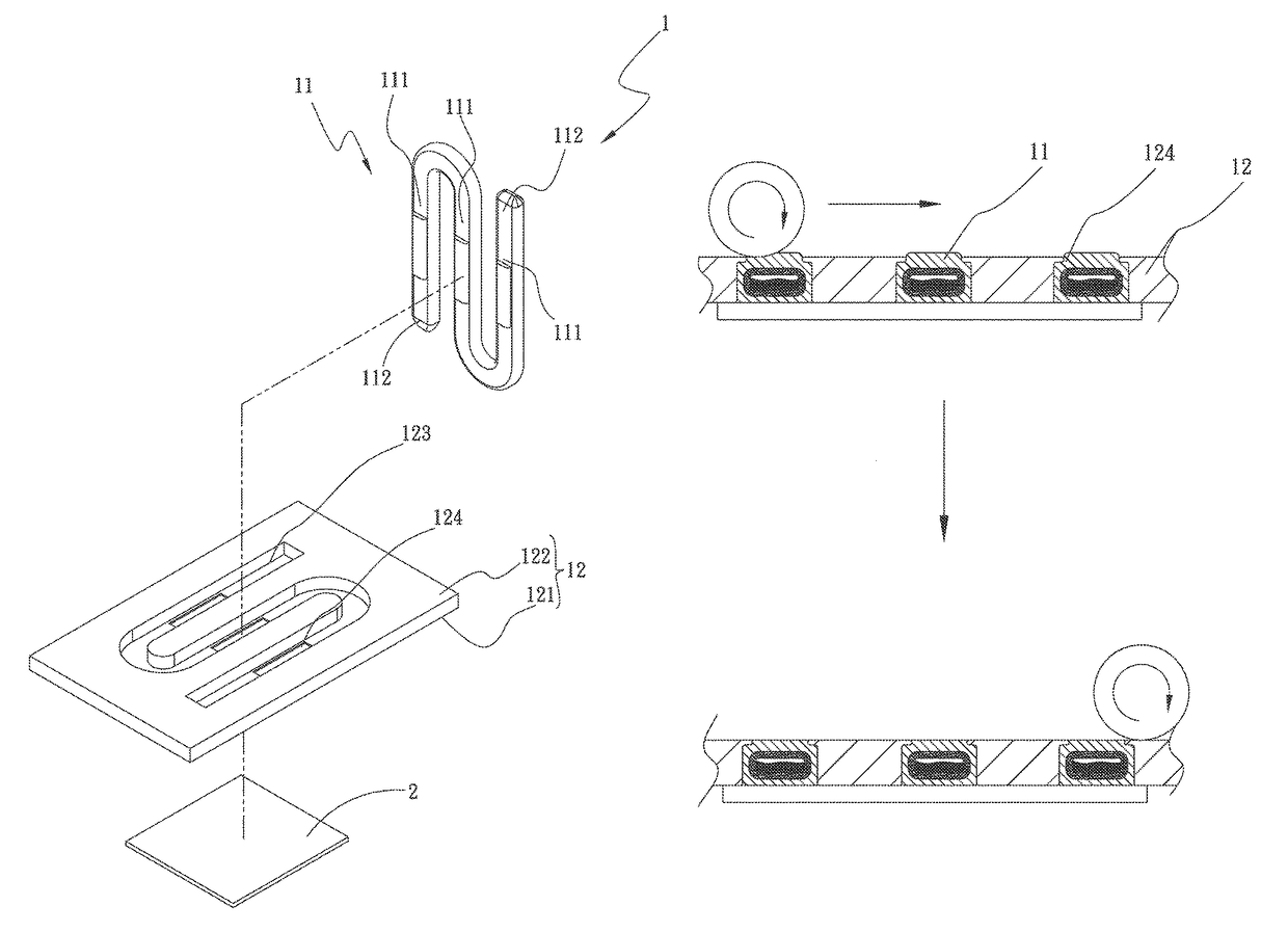
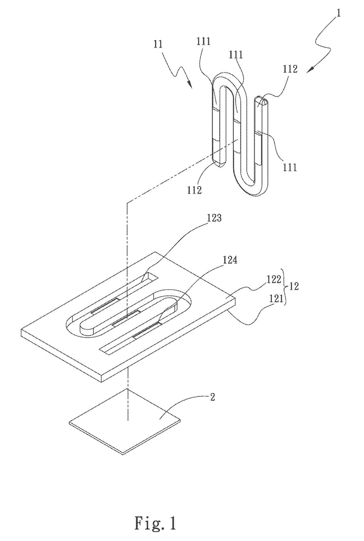
[0028]Please now refer to FIG. 4, which is a perspective exploded view of the heat dissipation unit of the present invention. In this embodiment, the heat pipe 11 is a circular heat pipe connected with the base seat 12. When the circular heat pipe 11 is placed into the channel 123 of the base seat 12 (the channel has an arched cross section in this embodiment), the heat pipe 11 partially protrudes from the channel 123 of the base seat 12. By means of mechanical processing (pressing and rolling), the section of the heat pipe 11 that protrudes from the channel 123 is forced into the channel 123 and filled into the perforations 124. Accordingly, the heat pipe 11 is shaped by the channel 123 and the perforations 124 and tightly bonded therewith. After mechanically processed and compressed, the heat pipe 11 may partially extrude from the perforations 124 and protrude from the first side 121 of the base seat 12. At this time, again by means of mechanical processing, the extruding part of ...

first embodiment

[0029]Please now refer to FIG. 7, which is a flow chart of the manufacturing method of the heat dissipation unit of the present invention. Also referring to FIGS. 1˜6, the manufacturing method of the heat dissipation unit includes steps of:

[0030]S1. providing a base seat and a heat pipe, a base seat 12 and a heat pipe 11 being provided, the base seat 12 being made of a material selected from a group consisting of copper, aluminum and an alloy thereof, the heat pipe 11 being selected from a group consisting of flat-plate heat pipe, D-shaped heat pipe and circular heat pipe;

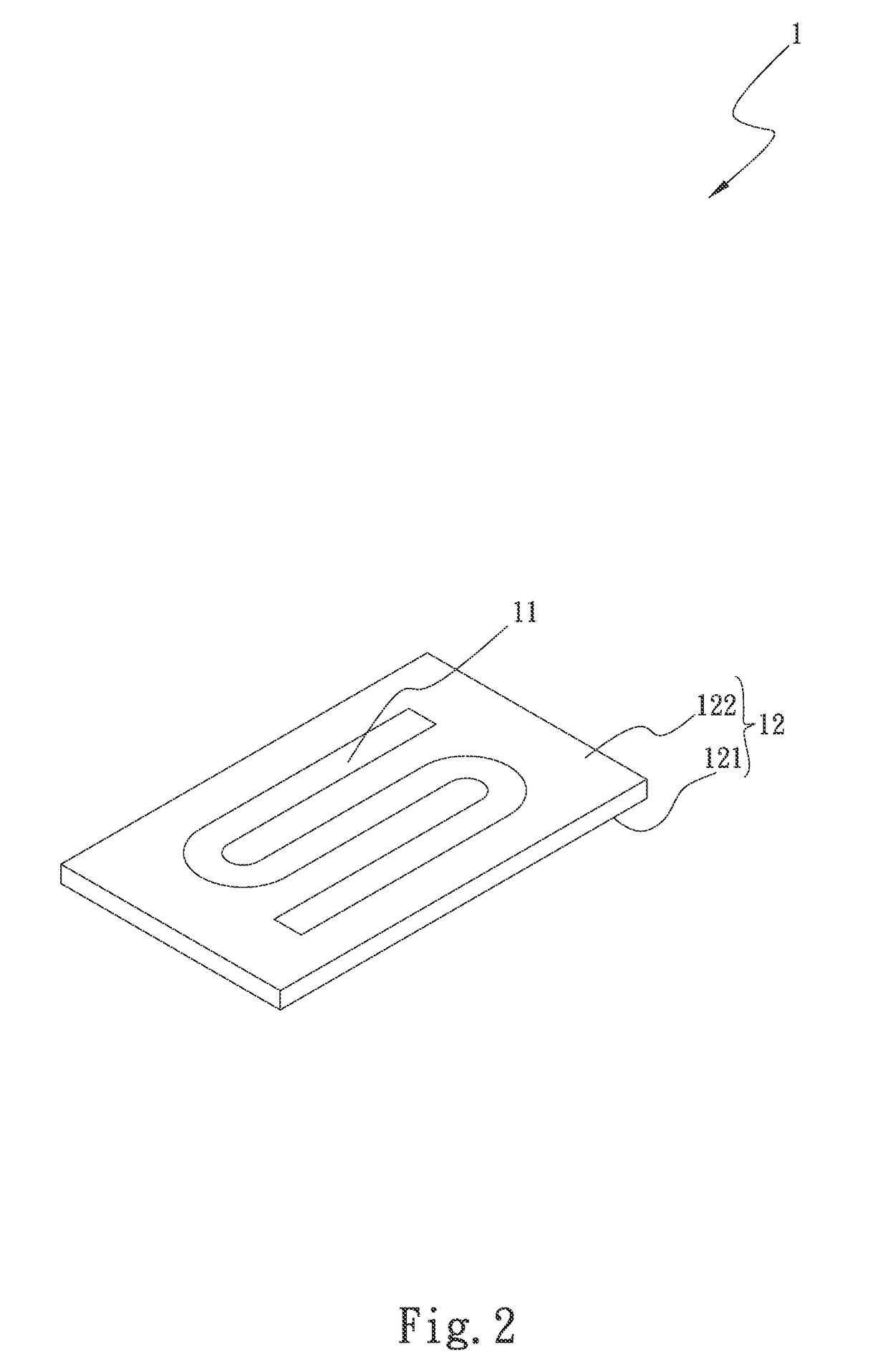
[0031]S2. forming a channel and multiple perforations on an upper face of the base seat, a channel 123 being formed on the upper face (the second side 122) of the base seat 12 by means of removing a part of the base seat 12, multiple perforations 124 being formed through the base seat 12 at the channel 123 near the center of the base seat 12 in communication with a lower face (the first side 121) of the base seat 1...


PUM

PropertyMeasurementUnit
flatnessaaaaaaaaaa
heat dissipation efficiencyaaaaaaaaaa
heat dissipationaaaaaaaaaa

Abstract

A heat dissipation unit manufacturing method is disclosed. The heat dissipation unit includes a heat pipe and a base seat. The base seat has a first side and a second side. The second side is formed with a channel and multiple perforations in communication with the first and second sides. The heat pipe has a heat absorption section and a conduction section. The conduction section extends from the heat absorption section in a direction to at least one end of the heat pipe distal from the heat absorption section. Several parts of the heat pipe corresponding to the perforations are received in the perforations and flush with the first side of the base seat. The heat dissipation unit manufacturing method improves the shortcoming of the conventional heat dissipation component that the coplanar precision between the heat pipe and the protruding platform of the base seat is hard to control.

Description

BACKGROUND OF THE INVENTION[0001]1. Field of the Invention[0002]The present invention relates generally to a heat dissipation unit manufacturing method, and more particularly to a heat dissipation unit manufacturing method to enable a heat dissipation unit to have a better heat contact plane face.[0003]2. Description of the Related Art[0004]A current electronic apparatus has a central processing unit and other calculation chips inside. In operation, all of the central processing unit and the calculation chips will generate heat. Therefore, a heat dissipation component is needed to help in increasing the heat dissipation efficiency so as to more effectively dissipate the heat. The most often used heat dissipation components are such as heat pipes, vapor chambers, heat sinks and radiating fins. These components serve to speed the heat conduction or transfer the heat to a remote end to dissipate the heat or enlarge the heat dissipation area to enhance the heat dissipation performance. ...

Claims


Application Information

Patent Timeline
Patent Type & Authority Patents(United States)
IPC IPC(8): B23P15/26
CPCB23P15/26B23P2700/09F28D15/0275F28F2275/12H01L21/4878H01L21/4882H01L23/427
Inventor LIN, SHENG-HUANG
Owner ASIA VITAL COMPONENTS SHENZHEN CO LTD
Why Eureka
Try Eureka