Apparatus for field-flow fractionation

a technology of apparatus and flow rate, applied in the field of apparatus for fieldflow fractionation, can solve the problems of limited dynamic region of flow rate, limited range of working pressure in which mass flow regulators may be used, delay in response time for flow rate control, etc., and achieve the effects of reducing cost and risk of failure, reducing cost and risk

Inactive Publication Date: 2018-02-20
POSTNOVA ANALYTICS
View PDF11 Cites 1 Cited by
  • Summary
  • Abstract
  • Description
  • Claims
  • Application Information

AI Technical Summary

Benefits of technology

[0015]Sequential splitting of the flows by means of suitable valves permits doing without the use of mass flow regulators. Instead, the flow split between the individual flow paths is achieved by the chronologically co-ordinated clocking of the switching of two valves in the apparatuses of the invention (one each in a first and a second flow path). In particular, the new flow scheme solves the problems described above in connection with the use of mass flow regulators with regard to the dynamic flow rate range and the necessary operating pressure as well as the flow rate sensitivity. This permits realizing a programmable focus flow with a concomitant reduction in components, resulting in a decrease of cost and the risk of failure.
[0099]The flow scheme of the apparatuses of the invention as described above is achieved by installing the first valve in the first flow path and the second valve in the second flow path. This makes it possible to do without commercial mass flow controllers for flow volume control. In particular, this solves the problem known from the prior art in connection with the use of mass flow controllers with regard to the limited dynamic range for the flow rates, the delayed response time for flow rate regulation and the limited operating pressure range and flow rate sensitivity. All in all, this permits realization of a programmable focus flow with a concomitant reduction of components which decreases both cost and the risk of failure.

Problems solved by technology

The main problem of mass flow controllers is the limited dynamic region for the flow rates, the delayed response time for flow rate control and the limited range of the working pressure in which mass flow regulators may be used.
Therefore, comparatively high technical effort was required until now to be able to use these mass flow regulators.
However, the needle valves required additional electronic components and a motor for control which meant extra components and thus extra cost.
Moreover, the use of needle valves increases the risk of failure as needle valves can easily get caught in the valve seat once they are fully closed.
In addition, needle valves tend to be soiled easily so that it will eventually become impossible to adjust the desired flow rates accurately.
The most recent developments in the area of high pressure valve technology permit extremely short switching times at high clock rates.
This permits realizing a programmable focus flow with a concomitant reduction in components, resulting in a decrease of cost and the risk of failure.
This results in interactions of the sample with the membrane so that parts of the sample adhere to the membrane and thus can no longer be eluted.
This makes precise statements about the sample concentration difficult.
As a result, a large number of samples tend to form aggregates.
Bore holes in the T-connector or the manifold used as the second flow volume splitting device with an internal diameter of more than 250 μm may result in broadening of the peaks and hence affect the measured value.
Given the problems resulting from pressure variations while the respective valves are being switched which are known in systems for field-flow fractionation this was not expected.

Method used


Image

  • Apparatus for field-flow fractionation
  • Apparatus for field-flow fractionation
  • Apparatus for field-flow fractionation

Examples


Embodiment Construction

[0126]In the following, preferred embodiments of the apparatuses of the invention will be explained with reference to the attached drawings and the reference numerals used there.

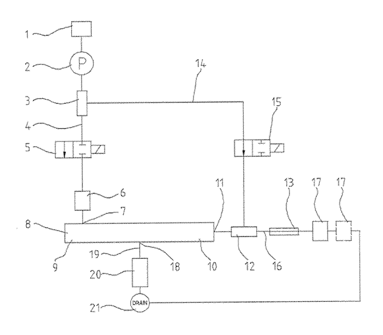
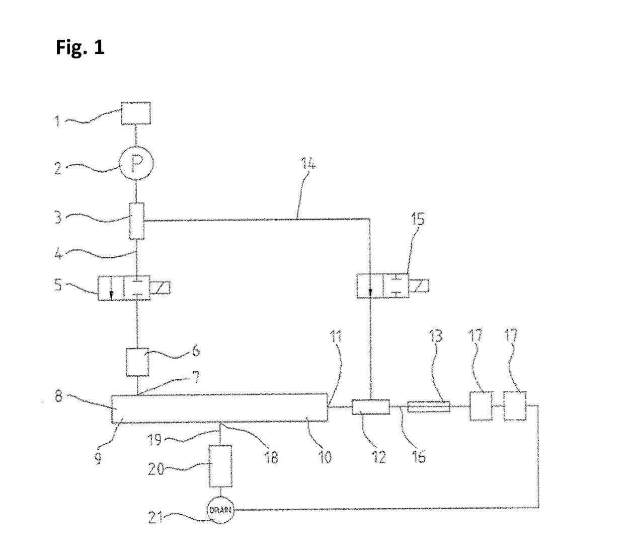
[0127]FIG. 1 shows the schematic design of an apparatus for field-flow fractionation according to the invention. Having passed a reservoir (1) and a pump (2), the volume flow is split via a T-connector (3) into a first flow path (4) and a second flow path (14). The first flow path (4) is initially guided to a first valve (5) and then, via an injector (6), to a first connector (inlet) (7) at a first end (9) of the separation channel (8). The separation channel can either be a hollow-fiber separation channel or an AF4 separation channel.

[0128]The second flow path (14) is guided to a second T-connector (12) via a second valve (15). This T-connector splits the volume flow between a second connector (outlet) (11) at a second end (10) of the separation channel (8) and a third flow path (16) which is guided to the ...


PUM

PropertyMeasurementUnit
flow rateaaaaaaaaaa
pressureaaaaaaaaaa
sizeaaaaaaaaaa

Abstract

The present invention relates to an apparatus for field-flow fractionation and to a method for separating samples by means of field-flow fractionation using this apparatus. The apparatuses of the invention comprise one or more reservoirs, a pump, a first flow volume splitting device, two valves for flow control, an injector, a separation channel having a first connector at a first end and a second connector at a second end or an AF4 separation channel having a first connector at a first end, a second connector at a second end and a third connector between the first and the second ends, optionally a second flow volume splitting device, a back-pressure element, one or more detector(s), a flow volume control device and one or more waste container(s). The apparatuses of the invention are characterized in that they comprise a valve for flow control in a first flow path and a second flow path which connect the pump to the first or the second or the third connector of the separation channel and that these valves are switched alternately in a controllable time ratio.

Description

TECHNICAL FIELD[0001]The present invention relates to an apparatus for field-flow fractionation and a method for the separation of samples by means of field-flow fractionation using said apparatus.PRIOR ART[0002]Field-flow fractionation (FFF) is a quasi-chromatographic method of analysis for separating macromolecular and colloidal samples. As opposed to chromatography, the separation of samples in field-flow fractionation does not take place in a packed column, but in an open separation channel which does not contain a stationary phase.[0003]Owing to the low height of the channel, a laminar flow with a parabolic flow profile is formed within the channel. Separation of the samples is carried out by a force field which is arranged vertically to this flow within the channel. Under the influence of the applied force field and the counter-acting diffusion of the sample particles, the individual components of the sample are separated. First, a state of equilibrium will occur in which the ...

Claims


Application Information

Patent Timeline
Patent Type & Authority Patents(United States)
IPC IPC(8): G01N1/00G01N30/32G01N30/00G01N30/38
CPCG01N30/32G01N30/0005G01N30/38G01N2030/328G01N2030/324G01N2030/326
Inventor KLEIN, THORSTEN
Owner POSTNOVA ANALYTICS
Why Eureka
Try Eureka