Anhydrous ammonia vapor charge unit for an applicator tank

a technology of ammonia vapor charge and applicator tank, which is applied in the direction of heat transfer, lighting and heating apparatus, and agriculture, can solve the problems of ammonia metering problems, ammonia has a foul odor, and problems that can arise, and achieve the effect of increasing the pressure charg

Active Publication Date: 2018-02-27
CONTINENTAL NH3 PROD CO
View PDF2 Cites 4 Cited by
  • Summary
  • Abstract
  • Description
  • Claims
  • Application Information

AI Technical Summary

Problems solved by technology

Although anhydrous ammonia has a foul odor and is hazardous as an inhalant, it is a very popular fertilizer for use on row crops.
These systems work fairly well, but under certain conditions problems can arise.
Problems often occur in metering ammonia since it expands in going from a liquid to a gas, often changing in volume in a ratio of one to eight hundred.
The metering problem is also exacerbated by the requirement of dividing the anhydrous ammonia into equal flow streams to allow equal distribution of the ammonia along the tool bars for a conventional row crop injection systems.
Dividing anhydrous ammonia into equal flow streams is also made more difficult by the flow of the liquid and vapor phases separating into different slip stream flows, which is not a homogenous mixture.
Applicator tanks are typically returned to ammonia supply distributors with ammonia still inside the tanks, yet with insufficient amounts of moisture low of a pressure to maintain an adequate supply for dividing on the tool bar.

Method used


Image

  • Anhydrous ammonia vapor charge unit for an applicator tank
  • Anhydrous ammonia vapor charge unit for an applicator tank
  • Anhydrous ammonia vapor charge unit for an applicator tank

Examples


Embodiment Construction

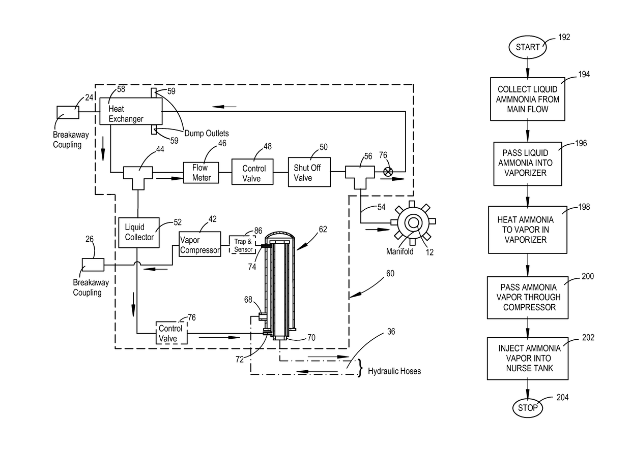
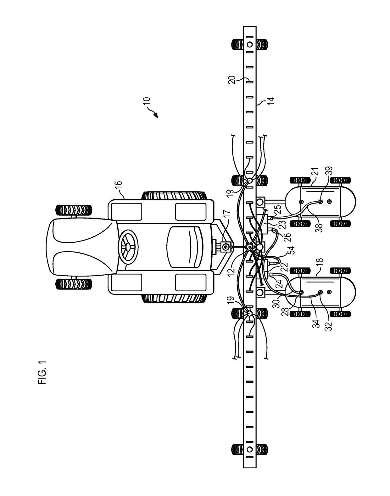
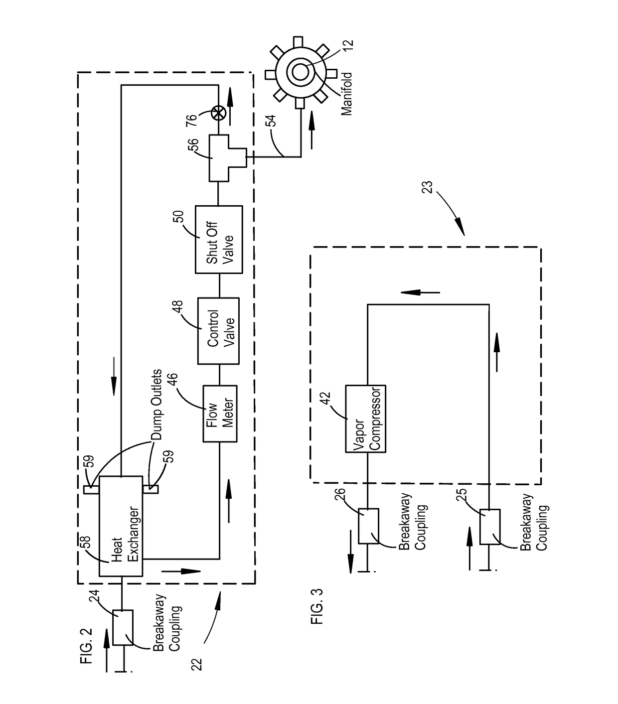
[0021]FIG. 1 is a top view a tractor 16 and an ammonia distribution system 10. The ammonia distribution system 10 includes an ammonia dividing manifold 12 mounted on a tool bar 14. The tractor 16 pulls the tool bar 14, an ammonia applicator tank 18, or nurse tank, and a secondary, caddy tank 21. An ammonia control unit 22 receives ammonia from the tank 18, then metered ammonia flows to ammonia dividing manifold 12, is divided, and then the divided flows are then further divided in sub-dividing manifolds 19 connected to applicator knives 20 mounted on tool bar 14. The applicator knives 20 inject precisely-metered and accurately-divided streams of ammonia liquid and vapor into the soil as the tractor 16 traverses an agricultural field. The control unit 22 has a breakaway coupling 24. A flow line 30 connects the breakaway coupling 24 to the outlet 28 and dip tube of the applicator tank 18. A vapor control unit 23 has a vapor compressor 42 and is mounted to the tool bar 14 and has a bre...


PUM


Abstract

An anhydrous ammonia vapor charge unit for an applicator tank maintains a pressure charge on an applicator tank. A secondary anhydrous ammonia tank is disposed adjacent to the applicator tank. Ammonia vapor from the secondary tank is passed through a vapor compressor and then is injected into the applicator tank to provide a greater pressure charge within the applicator tank. In a second embodiment, a small portion of a liquid flow stream of ammonia being removed from the applicator tank is separated from the flow stream, passed through a heat vaporizer for expanding from a liquid to a gas, passed through a vapor pressure, and then is injected into the applicator tank for maintaining the pressure charge on the applicator tank. Preferably the heat vaporizer used hydraulic fluid from a tractor to heat the anhydrous ammonia.

Description

CROSS REFERENCE TO RELATED APPLICATIONS[0001]The present application claims priority as a continuation in part of U.S. Provisional Patent Application Ser. No. 61 / 977,851 filed Apr. 10, 2014, entitled “Anhydrous Ammonia Heat Vaporizer for a Nurse Tank,” and invented by David P. Ward.TECHNICAL FIELD OF THE INVENTION[0002]The present invention relates in general to ammonia fertilizer application systems for agricultural use, and in particular to an ammonia fertilizer spreader having flow dividers which mix a vapor and liquid ammonia into a homogeneous mixture prior to dividing and passing the ammonia to respective ground injector knives.BACKGROUND OF THE INVENTION[0003]Anhydrous ammonia NH3 although first known as a refrigerant, is the lowest cost source of nitrogen for use as a fertilizer for fertilizing crops. Anhydrous ammonia NH3 is made from natural gas and air, and is 82% nitrogen and 18% hydrogen by weight. Although anhydrous ammonia has a foul odor and is hazardous as an inhala...

Claims


Application Information

Patent Timeline
Patent Type & Authority Patents(United States)
IPC IPC(8): A01C23/02F22B1/16F22B1/28
CPCA01C23/024F22B1/16F22B1/284
Inventor WARD, DAVID PSTRETCHER, JUDD K
Owner CONTINENTAL NH3 PROD CO
Why Eureka
Try Eureka