Method for manufacturing casting using lost wax process

a manufacturing method and technology of lost wax, applied in the direction of foundry moulding equipment, metal-working equipment, foundry patterns, etc., to achieve the effect of reducing production costs, rapid cooling, and eliminating drainage treatmen

Inactive Publication Date: 2018-02-27
CASTEM +1
View PDF11 Cites 2 Cited by
  • Summary
  • Abstract
  • Description
  • Claims
  • Application Information

AI Technical Summary

Benefits of technology

[0015]In the method for manufacturing a casting using a lost wax process according to the first aspect of the present invention, since the wax pattern forming die is the resin forming die that is sterically formed by using the stereolithography or the three-dimensional printer and has a heat resistance temperature higher than a temperature of the molten wax, even if a shape of the wax pattern forming die is frequently changed in case of, e.g., manufacturing a prototype on a preliminary step of manufacturing mass-produced items, the shape of the wax pattern forming die can be changed with a relatively few man-hours. That is, since fabrication of a die for forming the wax pattern requires a large amount of costs and changing the shape of this die requires a relatively large amount of costs, as compared with the conventional method for forming a wax pattern having a hollow structure requiring a large amount of costs, even if the shape of the cavity in the die is frequently changed in the present invention, changing the three-dimensional shape data used in the stereolithography or the three-dimensional printer can suffice, and hence the shape of the wax pattern forming die can be changed with a relatively few man-hours. Furthermore, since the evaporative pattern fabricated with the use of the stereolithography is made of the photocurable resin that is a different material from the wax, the wax pattern can be fabricated from the regular wax in the present invention as compared with the conventional method for manufacturing a precision casting mold that has the problem requiring special facilities and others to vanish the evaporative pattern made of the photocurable resin, and hence special facilities and others to vanish the wax pattern are not required.
[0016]In the method for manufacturing a casting using a lost wax process according to the second aspect of the present invention, since the plurality of wax patterns are fabricated in wax pattern fabrication and the plurality of wax patterns are bonded to the single casting sprue pattern in the form of a tree at the time of fabrication of the integrated pattern to fabricate the integrated pattern, the plurality of wax patterns can be fabricated in a relatively short time. That is, as compared with the conventional method for manufacturing a precision casting forming die by which a plurality of evaporative patterns must be sequentially fabricated based on the stereolithography which relatively takes time, a plurality of wax patterns can be fabricated based on injection molding or the like in a relatively short time in the present invention.
[0017]In the method for manufacturing a casting using a lost wax process according to the third aspect of the present invention, since the flow paths are formed in the wax pattern forming die in proximity to the inner surface of the cavity having the shape corresponding to the wax pattern, at the time of fabrication of the wax pattern using the wax pattern forming die, the cooling medium draws heat of the wax in the cavity by allowing the cooling medium to flow through the flow paths, and hence the wax pattern can be rapidly cooled. Consequently, the shape of the cavity in the wax pattern forming die can be precisely transferred to the wax pattern. Further, since the wax pattern forming die is formed by using the stereolithography or the three-dimensional printer, the flow path through which the cooling medium flows can be easily formed into a free shape.
[0018]In the method for manufacturing a casting using a lost wax process according to the fourth aspect of the present invention, the cooling medium is the pressurized air from the water tank pump, the wax is poured into the cavity and cooled down while keeping this pressured air flowing in from the inlet of the flow path and being discharged to the outlet of the flow path, and hence the air discharged from the outlet of the flow path can be emitted into the atmosphere as it is. Consequently, as compared with a case where a liquid which requires a drainage treatment is used as the cooling medium, the drainage treatment can be eliminated, and hence the cooling medium can be relatively easily handled.
[0019]In the method for manufacturing a casting using a lost wax process according to the fifth aspect of the present invention, since the concave portions which extend from the outer surface of the wax pattern forming die to the inside of the same close to the inner surface of the cavity having the shape corresponding to the wax pattern is formed in the wax pattern forming die, the heatsinks draw heat of the wax in the cavity by inserting the heatsinks into these concave portions, and the wax pattern can be rapidly cooled. Consequently, the shape of the cavity in the wax pattern forming die can be precisely transferred to the wax pattern. Further, since the wax pattern forming die is formed by using the stereolithography or the three-dimensional printer, the concave portions into which the heatsinks are inserted can be easily formed into a relatively free shape.

Problems solved by technology

Furthermore, the hollow structure forming member has solubility, and this hollow structure forming member is dissolved and removed from the wax pattern after the wax is cured.

Method used


Image

  • Method for manufacturing casting using lost wax process
  • Method for manufacturing casting using lost wax process
  • Method for manufacturing casting using lost wax process

Examples


second embodiment

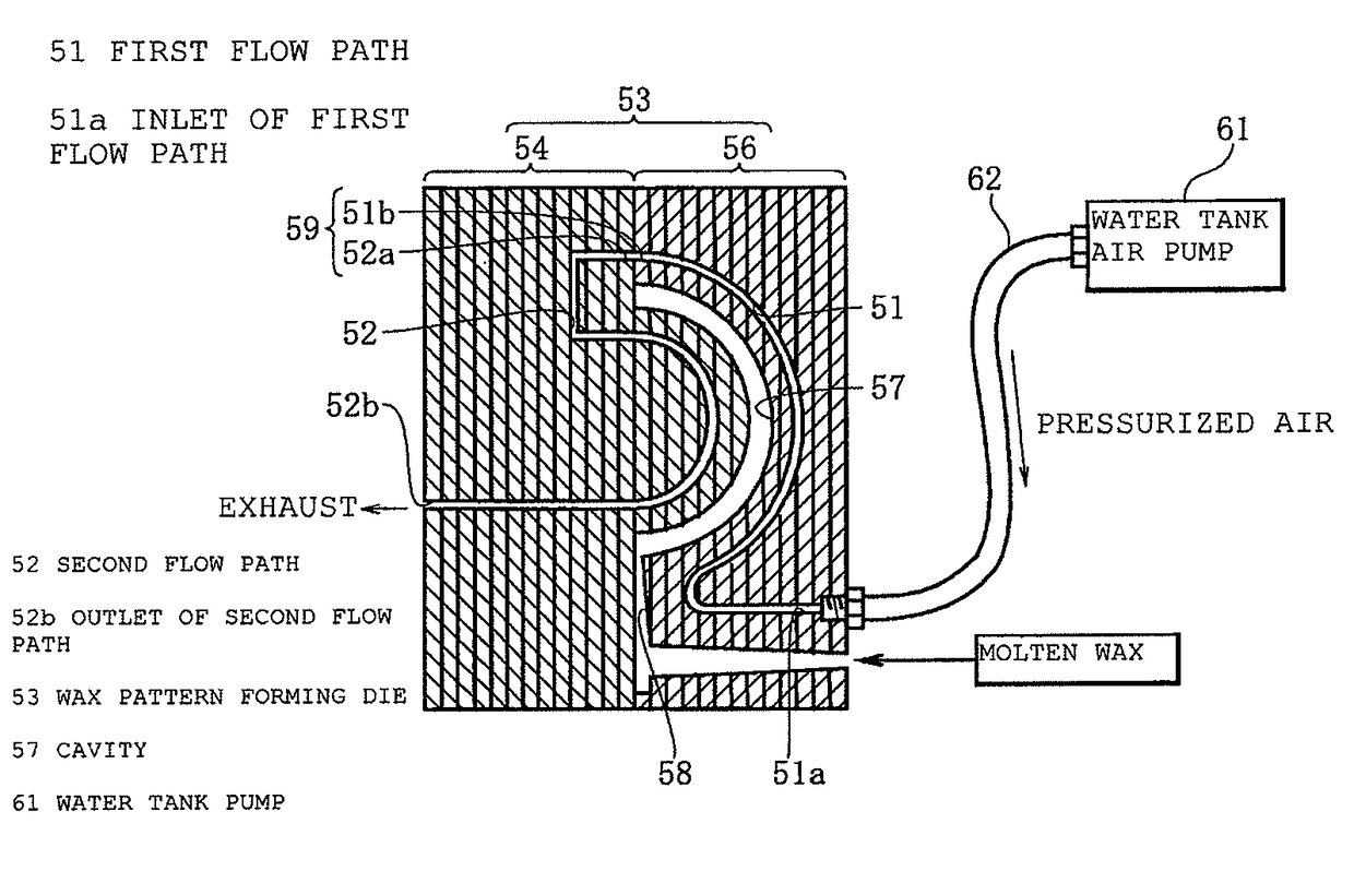
[0036]FIG. 5 shows a second embodiment according to the present invention. In this embodiment, at the time of fabricating a wax pattern forming die 53, first and second flow paths 51 and 52 are formed in the wax pattern forming die 53 in proximity to an inner surface of a cavity 57 having a shape corresponding to a wax pattern respectively so that a cooling medium can flow through these first and second flow paths 51 and 52. Specifically, in this embodiment, the wax pattern is formed into a bowl-like shape. Further, the wax pattern forming die 53 has a fixed side resin die 56 in which an outer surface of the cavity 57 for fabrication of the bowl-like wax pattern is formed and a runner 58 for pouring a molten wax into the cavity 57 is also formed, and a movable side resin die 54 in which an inner surface of the cavity 57 is formed. Furthermore, assuming that a volume of the cavity 57 is 1, a volume of the wax pattern forming die 53 is 40 to 200. The first flow path 51 through which t...

first embodiment

[0037]On the other hand, in mold clamping of the wax pattern forming die 53, an outlet 51b of the first flow path 51 and an inlet 52a of the second flow path 52 face to each other to form a connection port 59. Consequently, the first low path 51 and the second flow path 52 form one continuous flow path. In this embodiment, the cooling medium is the pressurized air from a water tank air pump 61, the wax is poured into the cavity 57 and cooled down while keeping the pressurized air flowing in from an inlet 51a of the first flow path 51 and flowing out from an outlet 52b of the second flow path 52 through the connection port 59. Specifically, an air pipe 62 of the single small water tank air pump 61 that operates with a power supply of 100 V is connected to the inlet 51a of the first flow path 51. This water tank air pump 61 is a pump that brings about aeration in a water tank for aquarium fish such as goldfish or tropical fish. Further, a known wax injection molding apparatus (not sho...


PUM

PropertyMeasurementUnit
melting temperatureaaaaaaaaaa
heat resistance temperatureaaaaaaaaaa
temperatureaaaaaaaaaa

Abstract

A wax pattern forming die to form a wax pattern is first fabricated, and a molten wax is poured into a cavity in the wax pattern forming die to fabricate the wax pattern. Subsequently, the wax pattern is bonded to a casting sprue pattern made of the wax and fabricated separately from the wax pattern to fabricate an integrated pattern, a surface of the integrated pattern is coated with ceramics, sintering is effected, then the integrated pattern is molten and effused to fabricate a mold to cast a casting with a casting sprue. Further, a molten metal is poured into the mold and cured, then the mold is crushed to take out the casting with the casting sprue, and the casting sprue is cut off from the casting with a casting sprue to fabricate a casting.

Description

TECHNICAL FIELD[0001]The present invention relates to a method for manufacturing a casting based on precision casting using a lost wax process. More specifically, the present invention relates to a method for manufacturing a casting by fabricating a wax pattern with the use of a wax pattern forming die fabricated by stereolithography or a three-dimensional printer.BACKGROUND ART[0002]There is disclosed a method for forming a wax pattern having a hollow structure by using a die including an upper die and a lower die (see, e.g., Patent Document 1). According to this method for forming a wax pattern having a hollow structure, a desired hollow structure is formed in the wax pattern before the wax pattern is taken out of the die. Further, a hollow structure forming member is arranged at a position corresponding to the hollow structure of the wax pattern of the die, and this hollow structure forming member is made of a wax and then removed from the wax pattern. Furthermore, the hollow str...

Claims


Application Information

Patent Timeline
Patent Type & Authority Patents(United States)
IPC IPC(8): B22C9/04B33Y80/00B22C9/06B22C7/02B33Y10/00
CPCB22C7/02B22C9/043B33Y80/00B33Y10/00B22C9/065
Inventor TODA, TAKUOSAGARA, SHUSAKUHASHIZUME, YOSHIHIRO
Owner CASTEM
Why Eureka
Try Eureka