Electrophotographic photoreceptor, method for manufacturing same, and electrophotographic apparatus using same

a photoreceptor and photoreceptor technology, applied in the field of electrophotographic apparatus using same, can solve the problems of increasing the void in the film, cracking in the film, deteriorating the functional materials of the film, etc., and achieves excellent operational stability, high sensitive, and highly durable

Active Publication Date: 2018-02-27
FUJI ELECTRIC CO LTD
View PDF57 Cites 0 Cited by
  • Summary
  • Abstract
  • Description
  • Claims
  • Application Information

AI Technical Summary

Benefits of technology

[0018]It is considered that the amount of residual solvent in the photosensitive layer can effectively be reduced by carrying out a drying step of drying the film at high temperature or increasing the processing time when manufacturing the photoreceptor. This method, however, not only easily leads to deterioration of the functional materials of the film due the heat, but also worsens the electrical properties of the photoreceptor, i.e., the sensitivity characteristics and residual potential characteristics of the photoreceptor, and hence the performance of the photoreceptor.
[0019]As a result of further investigation in view of these facts, the inventors have discovered that drying the film under reduced pressure is an effective way to reduce the amount of residual solvent at as low temperature as possible and within a short period of time without impeding the productivity. The inventors consequently have conceived the present invention based on their findings that a highly durable, layered positively-charge organic photoreceptor that is excellent in sensitivity and contamination resistance can stably be produced without impeding the electrical properties thereof or forming cracks even when sebum is adhered thereto.
[0024]With the configurations described above, the present invention can provide a highly sensitive and highly durable electrophotographic photoreceptor, a method for manufacturing the same, and an electrophotographic apparatus using the same, the photoreceptor being applicable to a high-resolution and high-speed positively-charged electrophotographic apparatus, being excellent in operational stability, providing no image defects that are the results of cracks generated due to image memories or contamination by contact members, grease, or sebum, and being capable of stably providing high image qualities.

Problems solved by technology

Such movement of the charge transport material increases the voids in the film.
Consequently, stress is concentrated on these enlarged voids, thereby creating cracks in the film.
This method, however, not only easily leads to deterioration of the functional materials of the film due the heat, but also worsens the electrical properties of the photoreceptor, i.e., the sensitivity characteristics and residual potential characteristics of the photoreceptor, and hence the performance of the photoreceptor.

Method used


Image

  • Electrophotographic photoreceptor, method for manufacturing same, and electrophotographic apparatus using same
  • Electrophotographic photoreceptor, method for manufacturing same, and electrophotographic apparatus using same
  • Electrophotographic photoreceptor, method for manufacturing same, and electrophotographic apparatus using same

Examples


example 1

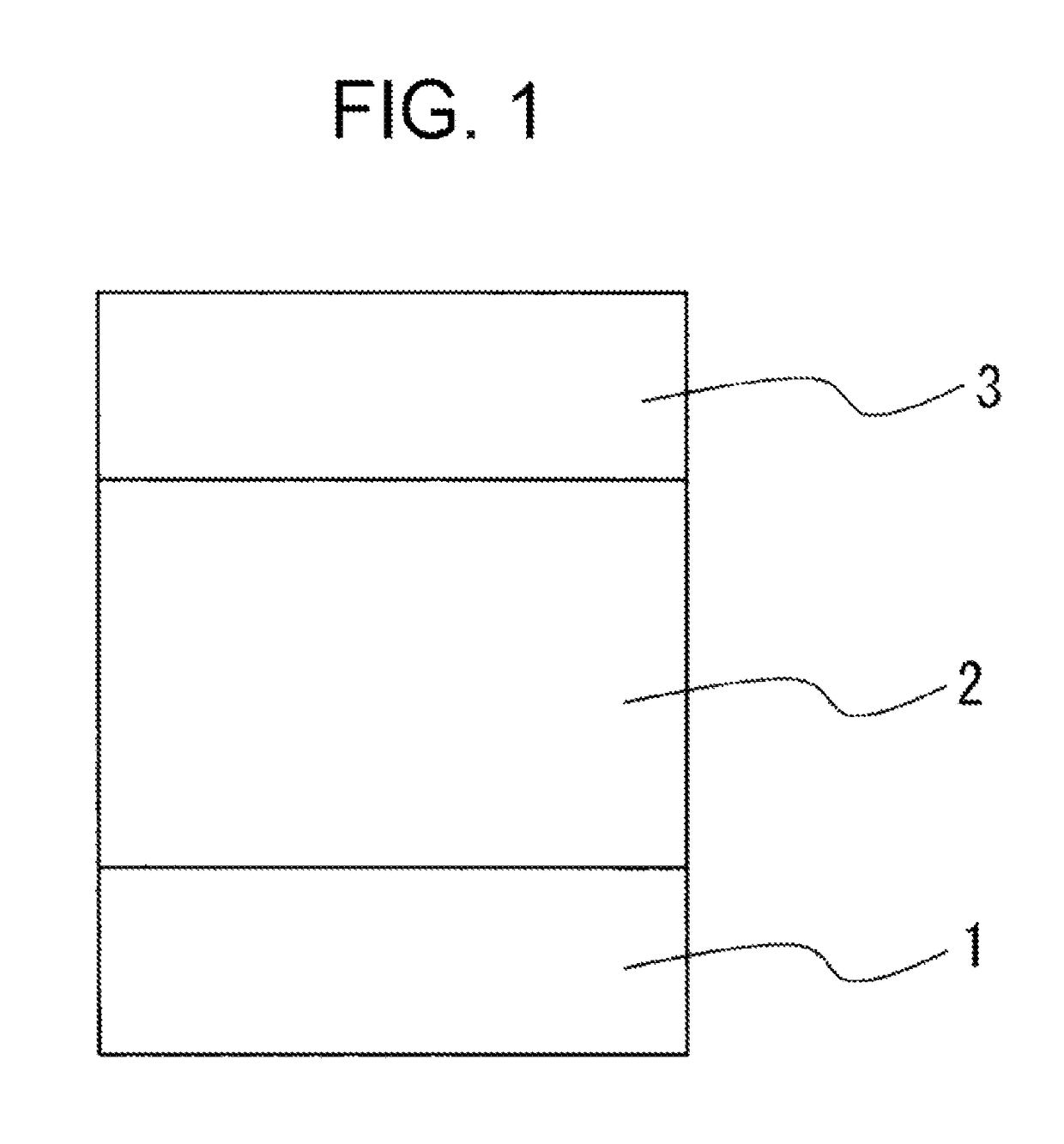
[0061]A 0.75 mm-thick aluminum tube having 30 mm in diameter and 244.5 mm in length and machined to have a surface roughness (Rmax) of 0.2 μm was used as the conductive support.

Production of Charge Transport Layer Coating Liquid

[0062]A styryl compound (CTM-A) shown in the following Structural Formula 1 in an amount of 100 parts by mass was prepared as the hole transport material, and 100 parts by mass of polycarbonate resin (TS2050, manufactured by TEIJIN LIMITED) (CTB-A) with a recurring unit shown in the following Structural Formula 2 was prepared as the binder resin. Then, these compounds were dissolved in a tetrahydrofuran solvent to produce charge transport layer coating liquid.

[0063]

Production of Charge Generation Layer Coating Liquid

[0064]With respect to 100 parts by mass of polycarbonate resin (CTB-A) same as the one prepared as the binder resin for the charge transport layer, 3 parts by mass of Y-type titanyl phthalocyanine shown in the following Structural Formula 3 as the...

example 2

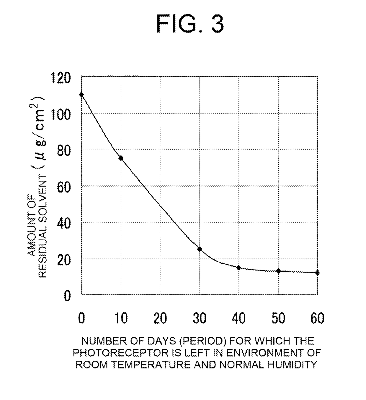
[0074]A charge generation layer was formed in the same manner as in Example 1, except that the coated charge generation layer was dried at 100° C. for one hour. After the formation of the charge generation layer, the charge generation layer was dried in a vacuum drying furnace at a pressure of 200 Pa and a temperature of 100° C. for 30 minutes, to obtain a photoreceptor of Example 2. In this photoreceptor, the total amount of residual solvents contained in the charge generation layer and the charge transport layer was 25 μg / cm2, and the total moisture content of the films was 0.05%.

example 3

[0075]The photoreceptor of Example 2 was left in a hot and humid environment of 60° C. and 90% RH for four hours, to obtain a photoreceptor of Example 3. In this photoreceptor, the total amount of residual solvents contained in the charge generation layer and the charge transport layer was the same as that of the photoreceptor of Example 2, but the total moisture content of the films was 0.33%.


PUM

PropertyMeasurementUnit
thicknessaaaaaaaaaa
boiling pointaaaaaaaaaa

Abstract

A layered, positively-charged electrophotographic photoreceptor, a method for manufacturing the photoreceptor and an electrophotographic apparatus using the photoreceptor are disclosed. The layered, positively-charged electrophotographic photoreceptor includes a conductive support on which is provided a sequential stack composed of a charge transport layer containing at least a first hole transport material and a first binder resin; and a charge generation layer containing at least a charge generation material, a second hole transport material, an electron transport material, and a second binder resin, wherein the charge generation layer and the charge transport layer have a total amount of residual solvents that is 50 μg / cm2 or less. The photoreceptor is highly sensitive, highly durable, and has excellent image qualities including low image defects from cracks generated due to image memory or contact contamination. The photoreceptor is applicable to a high-resolution and high-speed positively-charged electrophotographic apparatuses and provides excellent operational stability.

Description

CROSS-REFERENCE TO RELATED APPLICATION(S)[0001]This non-provisional Application for a U.S. Patent is the U.S. National Stage of and claims priority from International Application PCT / JP2011 / 067933 filed Aug. 5, 2011, the entire contents of which is hereby incorporated by reference.BACKGROUND OF THE INVENTION1. Field of the Invention[0002]The present invention relates to an electrophotographic photoreceptor (often simply referred to as “photoreceptor” hereinafter), a method for manufacturing the same, and an electrophotographic apparatus using the same. Particularly, the present invention relates to an electrophotographic photoreceptor used in an electrophotographic printer, copier, facsimile machine and the like, a method for manufacturing such an electrophotographic photoreceptor, and an electrophotographic apparatus using the same.2. Background of the Related Art[0003]Printers, copiers, facsimile machines, and other image forming apparatuses using the electrophotographic system in...

Claims


Application Information

Patent Timeline
Patent Type & Authority Patents(United States)
IPC IPC(8): G03G5/047G03G5/05G03G5/06B05D1/18G03G5/04
CPCG03G5/047B05D1/18G03G5/04G03G5/0696G03G5/0525G03G5/0564G03G5/0503
Inventor KITAGAWA, SEIZOTANAKA, YASUSHISUZUKI, SHINJIROEMORI, HIROSHINEBASHI, KAZUKI
Owner FUJI ELECTRIC CO LTD
Why Eureka
Try Eureka