Gas turbine engine component with integrated heat pipe

a technology of gas turbine engines and heat pipes, applied in the direction of machines/engines, indirect heat exchangers, light and heating apparatus, etc., can solve the problems of increasing heat loads, heavy brackets, and heavy weight of heat exchangers, and achieving the effect of reducing the capacity of such systems

Active Publication Date: 2018-03-06
GENERAL ELECTRIC CO
View PDF61 Cites 17 Cited by
  • Summary
  • Abstract
  • Description
  • Claims
  • Application Information

AI Technical Summary

Problems solved by technology

Known oil cooling systems for gas turbine engines typically include one or more air-to-oil heat exchangers, referred to as “air cooled oil coolers” or “ACOCs”, These heat exchangers can be heavy and have high drag, and can require special inlet and outlet ducts and large, heavy brackets.
Sometimes ACOCs are used in series with fuel-to-oil heat exchangers and fuel return-to-tank systems (“FRTT”) in a complex cooling network; however increasing heat loads are expected to exceed the capabilities of such systems.
But for flight critical fluids such as lubricating oil, a damaged heat exchanger is problematic as it could cause fires or critical loss of oil.

Method used


Image

  • Gas turbine engine component with integrated heat pipe
  • Gas turbine engine component with integrated heat pipe
  • Gas turbine engine component with integrated heat pipe

Examples


Embodiment Construction

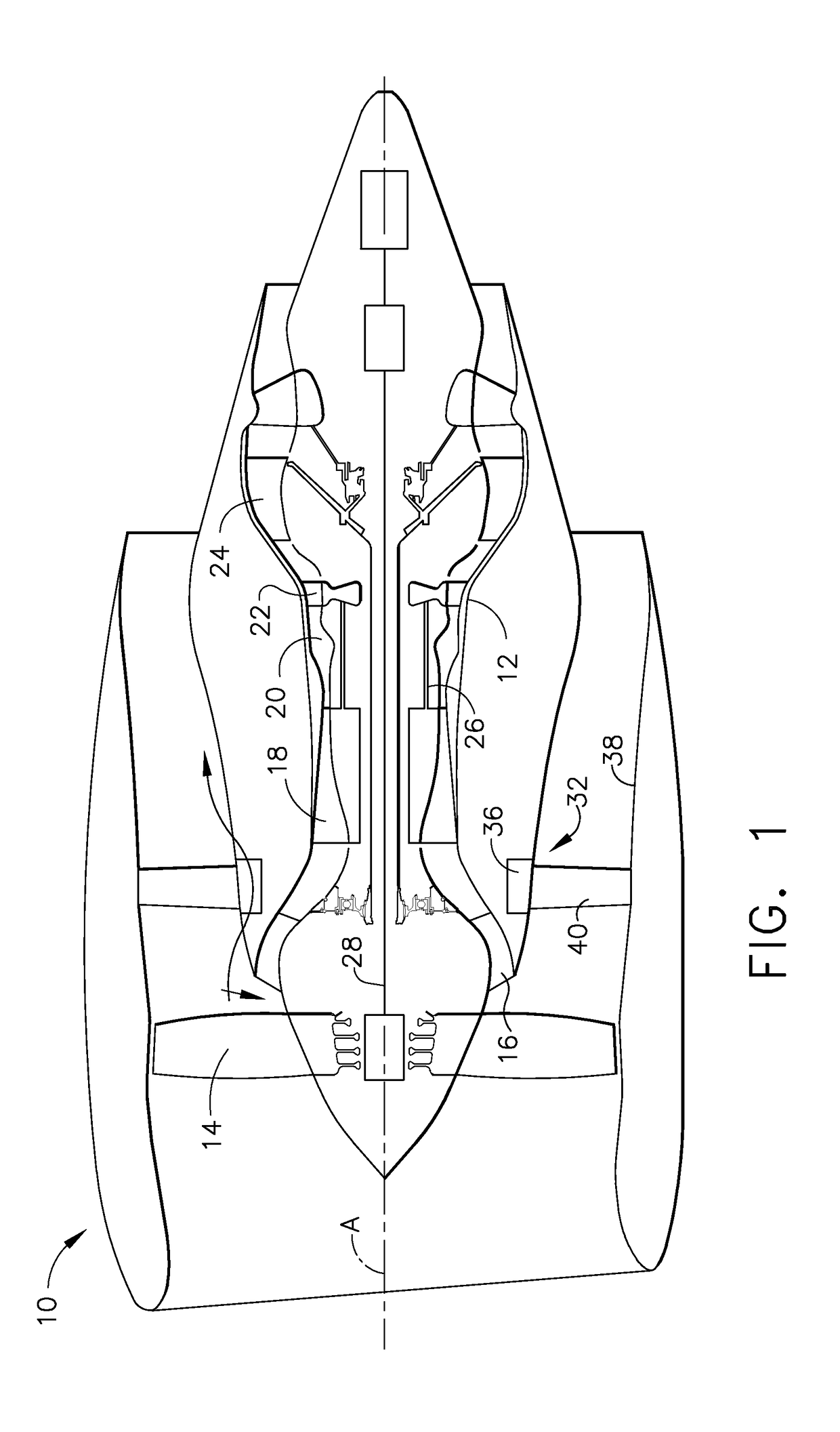
[0038]Referring to the drawings wherein identical reference numerals denote the same elements throughout the various views, FIG. 1 depicts a gas turbine engine 10 incorporating a heat exchanger apparatus constructed according to an aspect of the present invention. While the illustrated example is a high-bypass turbofan engine, the principles of the present invention are also applicable to other types of engines, such as low-bypass, turbojet, etc. The engine 10 has a longitudinal center line or axis A and an outer stationary annular casing 12 disposed concentrically about and coaxially along the axis A. The engine 10 has a fan 14, booster 16, compressor 18, combustor 20, high pressure turbine 22, and low pressure turbine 24 arranged in serial flow relationship. In operation, pressurized air from the compressor 18 is mixed with fuel in the combustor 20 and ignited, thereby generating combustion gases. Some work is extracted from these gases by the high pressure turbine 22 which drives...


PUM


Abstract

A heat transfer apparatus for a gas turbine engine includes: a component having a wall structure defining a flow bounding surface; a chamber formed in the component, the chamber including a wicking structure, a vapor channel, and a working fluid.

Description

BACKGROUND OF THE INVENTION[0001]This invention relates generally to gas turbine engines and methods for oil cooling in such engines.[0002]Gas turbine engines are commonly provided with a circulating oil system for lubricating and cooling various engine components such as bearings, gearboxes, electrical generators, and the like. In operation the oil absorbs a substantial amount of heat that must be rejected to the external environment in order to maintain the oil at acceptable temperatures. As engine designs evolve the amount of heat to be rejected is increasing.[0003]Known oil cooling systems for gas turbine engines typically include one or more air-to-oil heat exchangers, referred to as “air cooled oil coolers” or “ACOCs”, These heat exchangers can be heavy and have high drag, and can require special inlet and outlet ducts and large, heavy brackets. Sometimes ACOCs are used in series with fuel-to-oil heat exchangers and fuel return-to-tank systems (“FRTT”) in a complex cooling net...

Claims


Application Information

Patent Timeline
Patent Type & Authority Patents(United States)
IPC IPC(8): F01D9/04F01D25/12F01D25/18F02C7/14F01D5/18
CPCF01D25/12F01D5/181F01D9/04F01D9/041F02C7/14F01D25/18F05D2260/232F05D2220/32F05D2240/12F05D2260/208F02C7/12F28D15/046Y02T50/60
Inventor GERSTLER, WILLIAM DWIGHTKOSTKA, JAMES MICHAELRAMBO, JEFFREY DOUGLASMOORES, JOHN WILLIAM
Owner GENERAL ELECTRIC CO
Why Eureka
Try Eureka