
Resonant gyroscopes and methods of making and using the same

a gyroscope and high-frequency technology, applied in the field of microelectromechanical systems, can solve the problems of not meeting the performance level demanded by many high-end applications

Active Publication Date: 2018-03-13
GEORGIA TECH RES CORP
View PDF10 Cites 2 Cited by
  • Summary
  • Abstract
  • Description
  • Claims
  • Application Information

AI Technical Summary

Benefits of technology

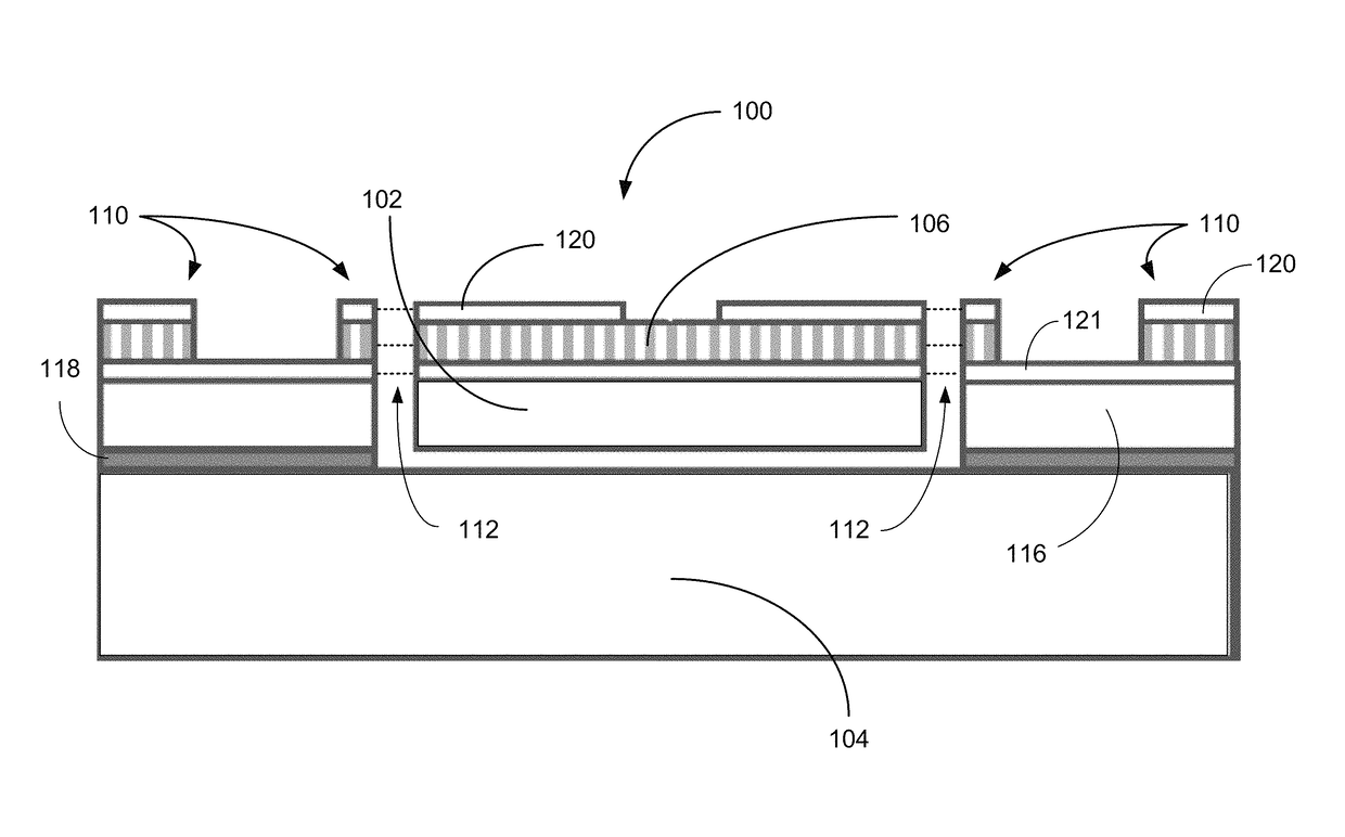
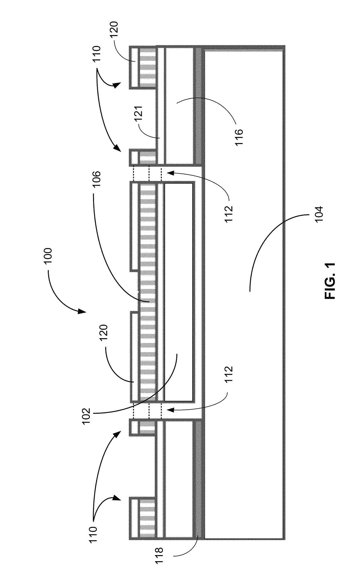
The patent text describes a technology for making high-frequency resonator gyroscopes. The technology involves a resonator body suspended adjacent to a substrate, with a ground electrode attached to the substrate and a piezoelectric layer attached to the ground electrode. A drive electrode is in electrical communication with the piezoelectric layer, and a sense electrode is in electrical communication with the piezoelectric layer. The technology also includes a tuning electrode in electrical communication with the piezoelectric layer, which matches the resonant frequency of the first vibration mode of the resonator body. The piezoelectric layer is composed of materials such as AlN, ZnO, PZT, GaN, and LiNbO3. The technology can be implemented in various ways, such as using a linear tuning circuit or a lock-in amplifier. The patent text also describes a method for making the gyroscope resonator.

Problems solved by technology

Although these vibratory gyroscopes provide the degree of functionality required by some consumer applications, they can fail to offer the performance level demanded by many high-end applications, such as short-range inertial navigation, while maintaining a micro-scale physical size.

Method used


Image

  • Resonant gyroscopes and methods of making and using the same
  • Resonant gyroscopes and methods of making and using the same
  • Resonant gyroscopes and methods of making and using the same

Examples


example 1

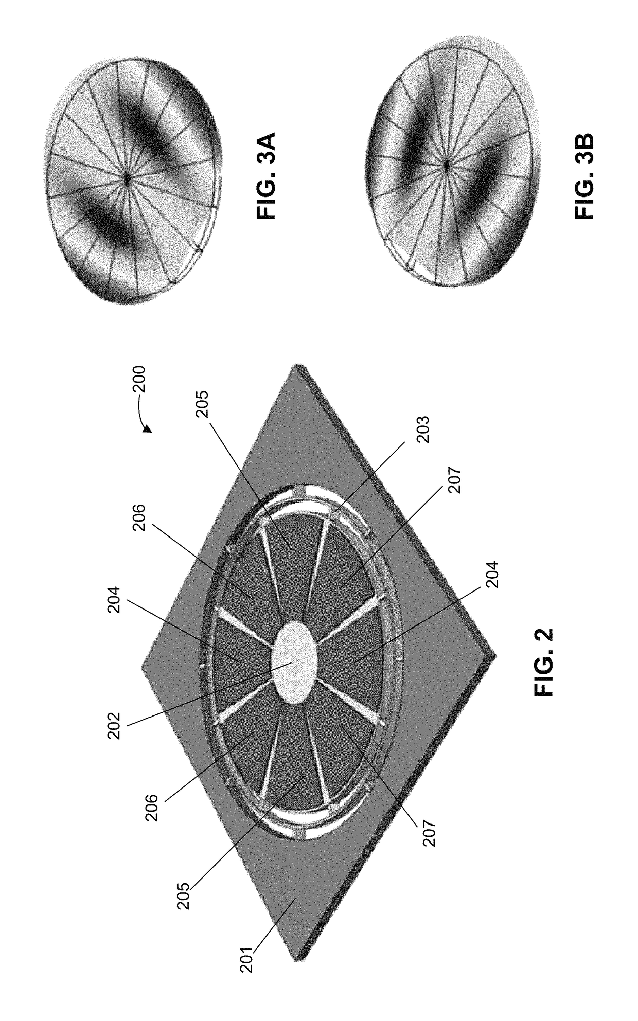
[0086]FIG. 9A-C shows the SEM images of a fabricated disk resonator gyroscope in accordance with some embodiments. In this embodiment, a 1-mm-diameter piezoelectrically transduced disk gyroscope comprised of a 1.3-μm thin film of AlN sandwiched between Molybdenum (Mo) electrode layers and stacked upon a 35-μm-thick (100) plate of single-crystal silicon. The bottom Mo electrode is used as the common terminal and the electrically-isolated top Mo electrodes are used for actuation, sensing and tuning of the gyroscope. The device was fabricated using a 4-mask AlN-on-Si process similar to the one described in W. Pan et al., “Thin-film piezoelectric-on-substrate resonators with Q enhancement and TCF reduction,” PROC. MICRO ELECTRO MECHANICAL SYSTEMS (MEMS), 727, 730 (2010).

[0087]In the embodiment depicted in FIGS. 9A-C, the gyroscopic coupling between the two degenerate in-plane flexural modes of a 1-mm-diameter disk structure having a resonance frequency of 4.34 MHz was verified by finite...

example 2

[0092]The gyroscopic coupling between the two orthogonal flexural mode pairs of a square resonator (A0) were modeled using a COMSOL Multiphysics simulation tool for a 300 μm×300×20 μm silicon square resonator having a thin ( direction of a (100) silicon plate. A quality factor (Q) of 3000, obtained from the measured results of a fabricated sample operating in air, was assumed for the resonance modes. The modeled resonator device was actuated by applying a 1.6 V (peak) harmonic signal to the drive electrode, resulting in the antinode displacement of ˜32 nm at the resonance frequency, which in turn induces Coriolis-induced current at the sense electrode when a finite rotation rate is applied.

[0093]FIG. 15 shows the simulated Z-axis rate response of the square gyroscope, resulting in a sensitivity of about 250 pA / ° / s per electrode. A mechanical noise equivalent rotation rate of 0.01 / Vs / A / Hz has been extracted for the square gyroscope operating in linear regime with a drive voltage of 1...

example 3

[0094]FIG. 16 shows the measured frequency response of an example gyroscope device operating in A0 mode (i.e. first flexural mode), observed from the drive input to sense output electrode. The observed frequency split of approximately 10 kHz (<1000 ppm) between the two modes is attributed to process non-idealities.

[0095]FIG. 17 depicts a measured response of an experimental piezoelectric gyroscope device to Z-axis rotation rates, as measured using a rate table and a read-out circuit (similar to the circuit 500 as shown in FIG. 5). In this example, the gyroscope device was excited in its first flexural mode (˜11 MHz) and characterized for different input rotation rates resulting in a sensitivity of 20.38 pV / ° / s for a sinusoidal drive voltage of 1.6 V (peak), which is comparable to capacitive BAW disk micro-gyroscopes with similar resonance frequency and drive / sense modes frequency.

[0096]The measured rate sensitivity is in close agreement with the value extracted from simulation (19.6...


PUM


Abstract

Certain implementations of the disclosed technology may include systems and methods for high-frequency resonant gyroscopes. In an example implementation, a resonator gyroscope assembly is provided. The resonator gyroscope assembly can include a square resonator body suspended adjacent to a substrate, a ground electrode attached to a side of the resonator body, a piezoelectric layer attached to a side of the ground electrode, a drive electrode in electrical communication with the piezoelectric layer, and configured to stimulate one or more vibration modes of the square resonator body; and a sense electrode in electrical communication with the piezoelectric layer, and configured to receive an output from the square or disk resonator responsive to stimulation of the one or more vibration modes.

Description

CROSS REFERENCE TO RELATED APPLICATIONS[0001]This application claims benefit, under 35 U.S.C. § 119(e), to U.S. Provisional Application No. 62 / 011,725 filed Jun. 13, 2014, entitled “High-Frequency AlN-on-Silicon Resonant Square Gyroscopes,” and to U.S. Provisional Application No. 62 / 104,508 filed Jan. 16, 2015, entitled “Piezoelectrically Transduced Resonant Disk Gyroscope.” The entire contents and substance of those applications are hereby incorporated by reference herein as if fully set forth below.STATEMENT OF FEDERALLY SPONSORED RESEARCH[0002]This technology was made with government support under contract HR0011-00-C-0032 awarded by the Defense Advanced Research Projects Agency (DARPA). The government has certain rights in the technology.TECHNICAL FIELD[0003]The various embodiments of the disclosure relate generally to microelectromechanical systems (MEMS), devices, and methods of making the same. More particularly, the embodiments relate to high-frequency resonant gyroscopes, a...

Claims


Application Information

Patent Timeline
Patent Type & Authority Patents(United States)
IPC IPC(8): H03J1/06G01C19/5684
CPCH03J1/06G01C19/5684H03J2200/19
Inventor AYAZI, FARROKHTABRIZIAN, ROOZBEHHODJAT-SHAMAMI, MOJTABANOROUZPOUR-SHIRAZI, ARASHK
Owner GEORGIA TECH RES CORP
Learn More