Interface and fluid-transfer system

a fluid transfer system and interface technology, applied in the field of interface and fluid transfer system, can solve the problems of requiring excessive handling, and reducing so as to reduce or eliminate product waste, increase flexibility, and improve the efficiency of the system.

Active Publication Date: 2018-03-20
MILLIPORE CORP
View PDF51 Cites 0 Cited by
  • Summary
  • Abstract
  • Description
  • Claims
  • Application Information

AI Technical Summary

Benefits of technology

[0033]Embodiments of the present invention have many advantages. Using a fluid transfer system including the interface device and transfer device(s) as described herein for sterile sampling of fluid from a reservoir can eliminate many steps in traditional sampling and post-sample handling processes. Sampling container types and sizes can be determined after the start of the process from which the samples are to be taken, allowing for increased flexibility. The system does not require tubes or manifolds, which can provide a more organized and efficient workspace. The sliding valve of the interface device does not contain any hold-up volume, which can reduce or eliminate product waste during the sampling process, thereby making embodiments of the present invention suitable for high value sampling applications. In addition, the sliding valve can be opened and closed repeatedly without trapping fluid in the valve. Advantageously, a large number of samples (e.g., 50 samples) can be taken from the process without the need to have the sample containers pre-attached to the interface device. The interface device provides an enclosed chamber, which is a previously sterilized, clean environment. The interface device enables the ‘clean’ environment to be isolated from a ‘dirty,’ external environment. The mating, rotating coupling elements help preserve sterility and process integrity as does the outer plunger. The plunger assembly allows for easy actuation of the sample with controlled volume measurements, which is another benefit for high value sampling applications. Another advantage of a fluid transfer system according the present invention is the absence of piercing needles, which increases process and operator safety.

Problems solved by technology

Attaching via manifolds, however, creates a hold-up volume (also referred to as deadleg), which is undesirable, and requires a flushing step, which can add cost and complexity to the given process.
A drawback of many current sampling systems is that they require excessive handling, as all single-use sampling containers must be pre-attached at once and prior to the start of a process.

Method used


Image

  • Interface and fluid-transfer system
  • Interface and fluid-transfer system
  • Interface and fluid-transfer system

Examples


Embodiment Construction

[0088]A description of example embodiments of the invention follows.

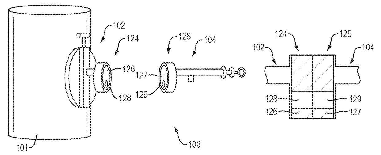
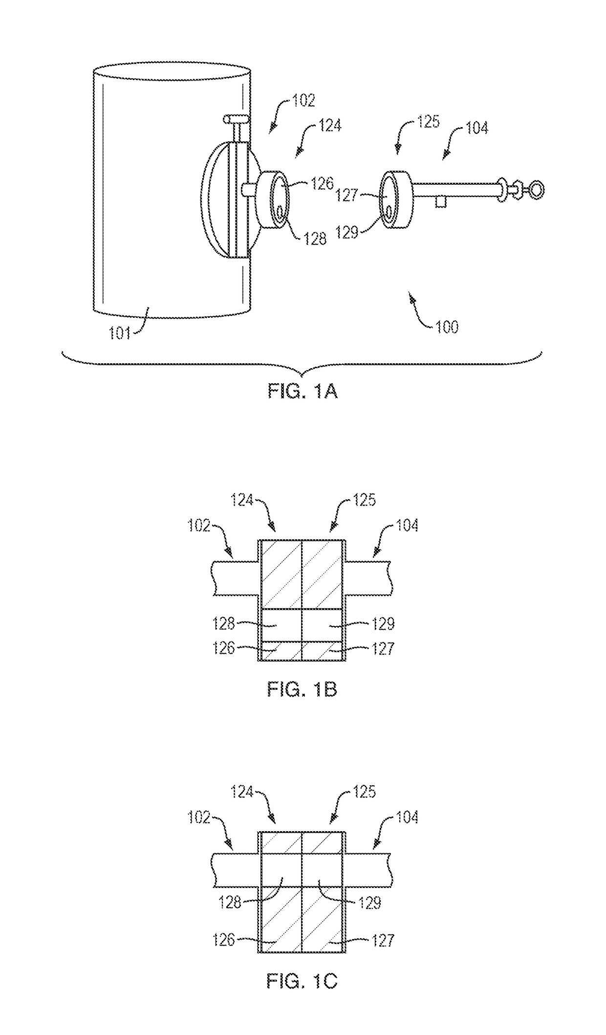
[0089]FIG. 1A is a schematic illustration of an example fluid transfer system 100 according to an embodiment of the present invention. The fluid transfer system 100 includes an interface device 102 to be mounted to a reservoir 101 and a transfer device 104 to be selectively coupled to the interface device 102. The interface device 102 includes a coupling member 124 that includes a sliding element 126 having an opening 128. The transfer device 104 includes a coupling element or member 125 that includes a sliding element 127 having an opening 129. In FIG. 1A, the interface and transfer devices 102 and 104 are shown uncoupled. The coupling members 124 and 125 are in respective closed positions, the opening 128 being out of alignment with the interface device 102 and the opening 129 being out of alignment with the transfer device 104. The transfer coupling member 125 is configured to couple to the interface coupling mem...


PUM

PropertyMeasurementUnit
rotationaaaaaaaaaa
diameteraaaaaaaaaa
sizeaaaaaaaaaa

Abstract

A fluid transfer system (100) includes a transfer device (104) and an interface device (102). The transfer device (104) includes a fluid transfer member (164) and a transfer coupling member (125) to align the fluid transfer member (164) with the interface device (102). The interface device (102) includes a reservoir port (108), a fluid transfer member receptacle (144), an interface coupling member (124), and a reservoir valve (110). The interface coupling member (124) is configured to close the fluid transfer member receptacle (144) and to couple to the transfer coupling member (125) and open the fluid transfer member receptacle (144) to receive the fluid transfer member (164). The reservoir valve (110), e.g., a sliding seal, is configured to close the reservoir port (108) from the fluid transfer member receptacle (144) and to open the reservoir port (108) to the fluid transfer member (164) when the fluid transfer member (164) is positioned in the fluid transfer member receptacle (144). The fluid transfer member (164) can include a plunger assembly configured to open and close the reservoir port (108).

Description

RELATED APPLICATION[0001]This application is the U.S. National Stage of International Application No. PCT / US2013 / 075460, filed on Dec. 16, 2013, which designates the U.S., published in English, and claims the benefit of U.S. Provisional Application No. 61 / 738,265 filed on Dec. 17, 2012. The entire teachings of the above applications are incorporated herein by reference.BACKGROUND OF THE INVENTION[0002]There are many aseptic and sterile sampling systems on the market today. Often, the sampling systems connect to a vessel via a sanitary connection (typically, a standard port of 0.75″, 1.5″ or 2″ in diameter). Some systems are actuated by a valve mechanism while others employ a needle to pierce a septum. In general, the number of samples that can be taken may be limited by any of the following aspects: size of the septum (piercing multiple times at one site is generally not accepted in the industry), size and number of the containers (bags, bottles, etc.) that can be attached to the ve...

Claims


Application Information

Patent Timeline
Patent Type & Authority Patents(United States)
IPC IPC(8): G01N1/20G01N1/22F16K3/04G01N1/10
CPCF16K3/04G01N1/10G01N1/2226G01N1/22G01N2001/1037
Inventor SARAGOSA, JOHNCIECIUCH, JOHNKELLY, JAMES E.MESSIER, LUCVIGORITO, NICHOLAS
Owner MILLIPORE CORP
Why Eureka
Try Eureka