Floor scrubber dry sweep apparatus

a floor scrubber and dry sweep technology, applied in the direction of floor scrubbers, vacuum cleaners, carpet cleaners, etc., can solve the problems of ineffective saturated dry filter, and inability to clean the surface of the floor,

Active Publication Date: 2018-03-27
MINUTEMAN INT
View PDF6 Cites 7 Cited by
  • Summary
  • Abstract
  • Description
  • Claims
  • Application Information

AI Technical Summary

Benefits of technology

[0012]The present invention incorporates various improvements in combined wet floor scrubber and drysweeper machines which removes and stores dust and debris removed from the floor using a solution application system and a squeegee arrangement for removing dust and recovering used solution from the floor and eliminating problems associated with the use of a dry dust filter with a solution applied to, and recovered from, the floor. Plural flexible skirts, or baffles, are positioned around the periphery of a scrub head having a pair of closely spaced, counter-rotating scrub brushes to confine and channel dust removed from the floor. The brushes direct dust and debris removed from the floor rearwardly and upwardly into a debris hopper as in the typical scrubbing operation. The dust is directed rearwardly by the skirts to a channel formed by a lower surface of the debris hopper and the floor, with the dust then directed to an aft squeegee disposed in a slightly raised position above the floor. Coupled to the squeegee is a generally vertical squeegee vacuum hose which is also coupled to a vacuum fan, or impeller, for drawing the dust upwardly to a solution recovery tank. Water in the form of a mist is directed onto the dust drawn upwardly through the squeegee vacuum hose, with the water particles adhering to and depositing the dust particles in the solution recovery tank. A demister disposed in, or adjacent to, an upper portion of the recovery tank separates the remaining water vapor from the air, and the dry air is drawn through the vacuum impeller for discharge from the scrubber / sweeper combination into the atmosphere.

Problems solved by technology

Field use has demonstrated that there is a basic problem with this type of dry sweep system.
The dry sweep dust filter, even though not used when scrubbing and not transmitting air during scrubbing operations, becomes saturated and clogged with moisture and wet debris primarily due to its close proximity to the debris hopper.
As a result, the saturated dry filter becomes ineffective when needed as a dry dust filter.
Due to the relatively small debris hopper volume and other considerations, scrubbers used as dry sweepers are not intended to be as effective as a dedicated floor sweeper.

Method used


Image

  • Floor scrubber dry sweep apparatus
  • Floor scrubber dry sweep apparatus
  • Floor scrubber dry sweep apparatus

Examples


Embodiment Construction

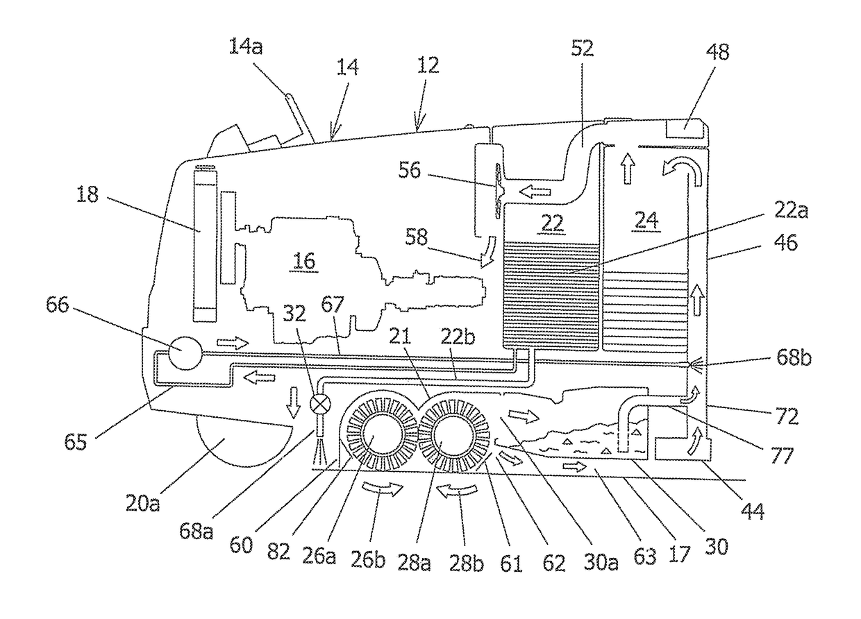
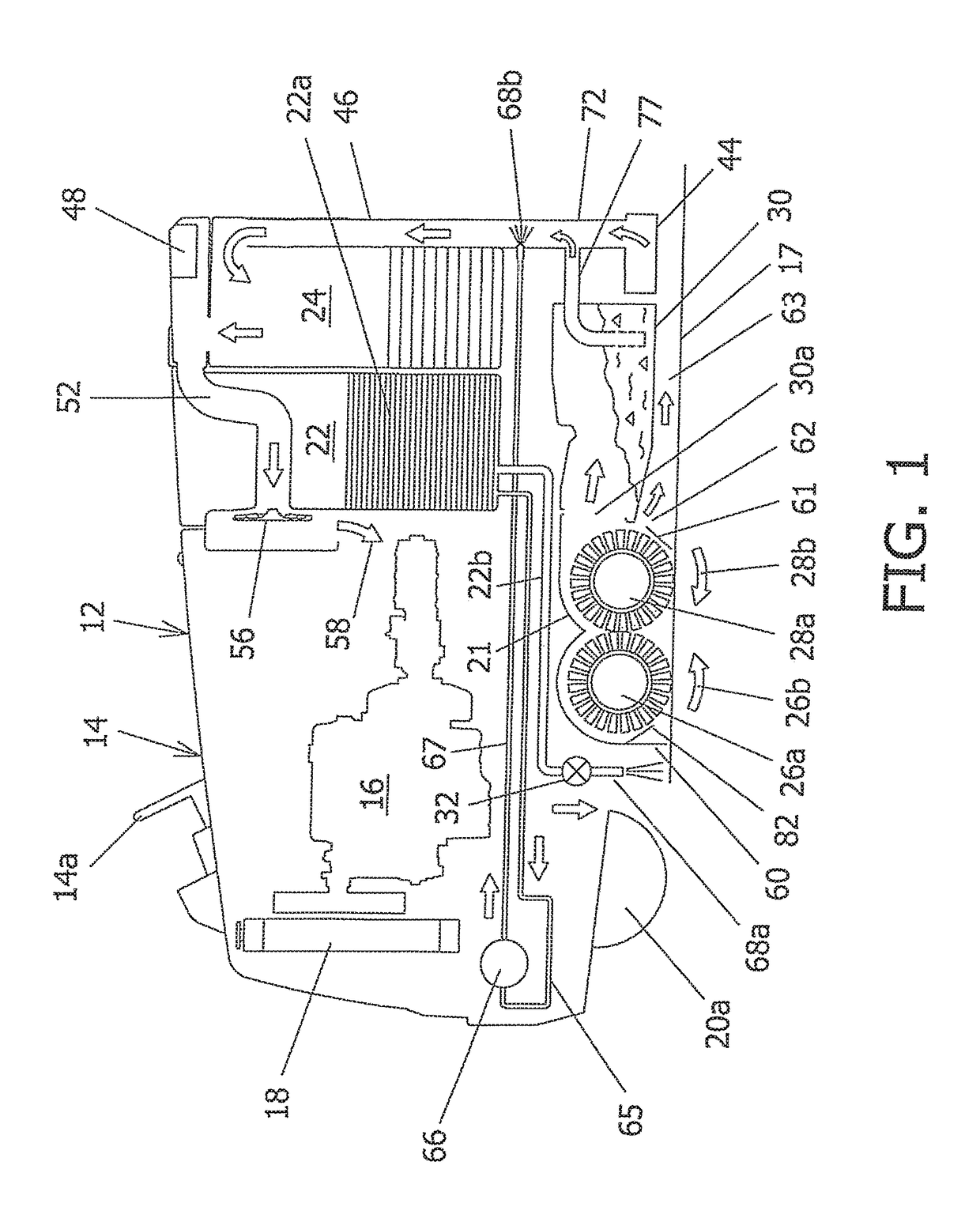
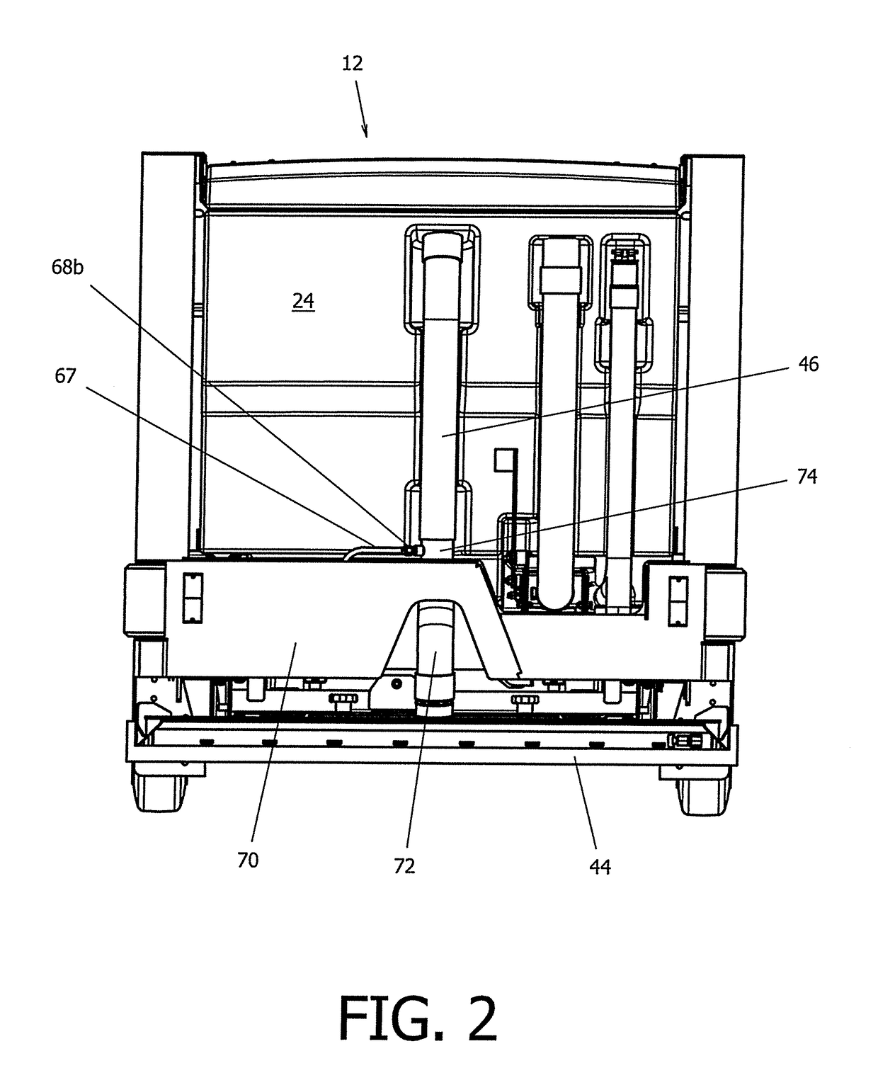
[0017]Referring to FIG. 1, there is shown a vertical cross sectional view of a combination floor sweeper and scrubber apparatus 12 in accordance with the present invention taken along the length of the apparatus. FIG. 2 is an aft, generally planar view of the inventive floor scrubber dry sweep apparatus 12, while FIG. 3 is a perspective view of a bottom portion of the apparatus illustrating a scrub head 21 including first forward and a second aft rotating scrub brushes 26a and 28a. The combination floor sweeper and scrubber apparatus 12 includes a chassis 14 which incorporates the various components and systems described in the following paragraphs. For example, the apparatus includes a steering wheel 14a, plural wheels, where one of the front wheels as shown as element 20a which is disposed upon and engages a floor 17. In addition, the combination floor sweeper and scrubber apparatus 12 further includes an engine 16 for displacing the floor sweeper and scrubber apparatus over the f...


PUM


Abstract

An industrial floor scrubber includes a solution tank and delivery system for applying the solution to the floor, and one or more rotating brushes for removing dust and debris from the floor and respectively directing same to a squeegee and to a debris hopper. The trailing squeegee removes the remaining solution from the floor and, in combination with a vacuum system, directs the recovered solution to a cleaning solution recovery tank in the scrubbing mode of operation. In a sweeping mode of operation, the use of a dust filter is eliminated as the dust-laden air is directed past the debris hopper and onto the upraised squeegee which confines and directs the dust-laden air into a spray of fine water particles which adhere to and transport the dust-bearing water particles to the recovery tank via an applied vacuum. The heavy dust-bearing water particles drop into the recovery tank, while a demister removes the remaining water vapor with the dry air discharged to the atmosphere via a vacuum impeller.

Description

FIELD OF THE INVENTION[0001]This invention relates generally to apparatus and a method for maintaining and conditioning a generally flat surface, and is particularly directed to the scrubbing and sweeping of a floor surface using a single apparatus which is easily converted between a wet scrubbing / sweeping mode of operation, and a dry sweeping operation without changing or replacing any components or systems.BACKGROUND OF THE INVENTION[0002]Industrial floor scrubbers typically include a cleaning solution tank, a solution delivery system to apply the cleaning solution to the floor in front of one or more rotating cylindrical or disc scrub brushes for cleaning the floor, a squeegee located aft of the scrub brushes for drying the floor, a vacuum system for reclaiming the cleaning solution, and a recovery tank for holding the reclaimed cleaning solution. In addition, floor scrubbers that employ cylindrical scrub brushes are frequently provided with a debris hopper located aft of the scr...

Claims


Application Information

Patent Timeline
Patent Type & Authority Patents(United States)
IPC IPC(8): A47L11/29A47L11/30A47L11/40A47L11/24
CPCA47L11/302A47L11/4016A47L11/4041A47L11/4044A47L11/4083A47L11/4088A47L11/24A47L11/28A47L11/40A47L7/0004A47L11/202
Inventor PERSON, BARRY M.SHEEHAN, KEVIN P.KNOWLTON, CHRISTOPHER M.
Owner MINUTEMAN INT
Why Eureka
Try Eureka