Method for producing components from fiber-reinforced composite material

a composite material and fiber reinforcement technology, applied in the direction of synthetic resin layered products, transportation and packaging, other domestic articles, etc., can solve the problems of increasing production costs, increasing production costs, and difficulty in reducing the elimination rate at the end of the production line, so as to reduce the elimination rate and reduce the elimination rate , the effect of reducing the elimination ra

Active Publication Date: 2018-03-27
MUBEA CARBO TECH GMBH
View PDF21 Cites 2 Cited by
  • Summary
  • Abstract
  • Description
  • Claims
  • Application Information

AI Technical Summary

Benefits of technology

[0014]For economic reasons, with sophisticated production lines it is traditionally sought after each production step to eliminate defective intermediate products, so that these do not cause any unnecessary additional systemic, wage or material costs in subsequent production steps and thereby achieving a low elimination rate at the end of the production line. When producing composite components, however, this type of procedure for reducing elimination rates at the end of the production line often proves difficult. One of the main reasons for this is that, generally speaking, when producing high-quality composite components, what is known as an integral construction is sought. This production concept seeks to produce as many functional elements of a product as possible simultaneously in a single production operation, so as, for example, to cut later assembly costs. In addition, in the case of transfer molding for example (known as “resin transfer molding”, hereinafter “RTM”), this concept allows for cost-effective production of high-quality components which are easily reproducible in middle and mass production. However, since this does away with multiple production steps involved in conventional (sophisticated) construction, this also means that successive checks on intermediate products are no longer possible. Although it is indeed possible to reduce the risk of a defective component being produced in such an integrated method step as a result of a large number of measures, this also leads to increased production costs, for which reason a compromise normally has to be found between risk minimization and additional costs.

Problems solved by technology

When producing composite components, however, this type of procedure for reducing elimination rates at the end of the production line often proves difficult.
However, since this does away with multiple production steps involved in conventional (sophisticated) construction, this also means that successive checks on intermediate products are no longer possible.
Although it is indeed possible to reduce the risk of a defective component being produced in such an integrated method step as a result of a large number of measures, this also leads to increased production costs, for which reason a compromise normally has to be found between risk minimization and additional costs.
Particularly problematic are categories of defects which cannot be corrected and at the same time can be neither efficiently prevented not detected before completion of the method step.
These differences cause an irregular surface sheen and can result in reinforcement fibers penetrating the paint surface.
A third type is the undesirable creation of large pores as liquid matrix systems are fed into cavities.
Such reworking is, however, hardly economical for medium- and mass production and, what is more, in many cases the quality of the surface finish obtained falls short of the aesthetic requirements placed by end consumers on the component.
Furthermore, individual reworking operations entail high costs and are time-consuming.
From a production perspective, this is also problematic primarily because this elimination of components due to defects in their surface condition does not occur until a large share of the production costs has already been incurred.
This not only directly increases the costs per defect-free component, but it also reduces production capacities.
The disposal of finished components solely on the ground of small irregularities in the surface structure is therefore problematic from an environmental perspective as well.

Method used


Image

  • Method for producing components from fiber-reinforced composite material
  • Method for producing components from fiber-reinforced composite material

Examples


Embodiment Construction

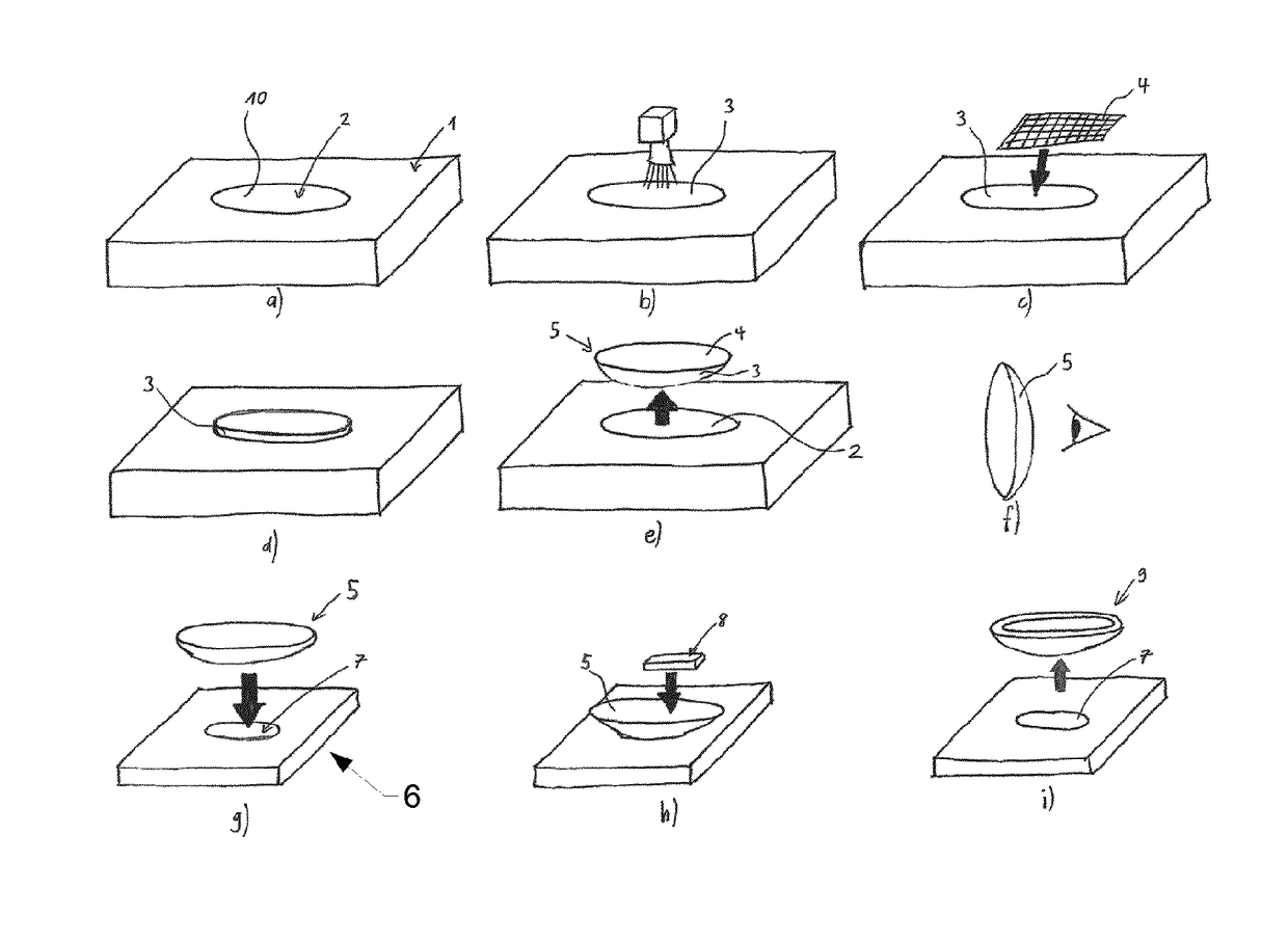
[0034]A method according to the invention is explained in more detail with reference to FIG. 1. Put simply, the method according to the invention shown comprises the following method steps: in a first step (cf. FIG. 1a) a molding tool 1 having a cavity 2 is provided. The cavity 2 has a shaping wall 10.

[0035]If required, as shown in FIG. 1b, a surface layer 3 is applied to the wall 10 (or to parts thereof), so that said surface adheres temporarily to said wall. Depending on the embodiment, a plurality of plies of surface layers may even be applied. The one or more surface layers 3 may consist, for example in their raw state, of a liquid and / or a powder and / or a film. Generally speaking, these reach their desired properties only as a result of processing. In one embodiment, the surface layer 3 is treated by the action of electromagnetic waves prior to application of a first ply of fibers. In particular, provision is made for the use of radiation at wavelengths in the infrared or ultra...


PUM

PropertyMeasurementUnit
conductiveaaaaaaaaaa
adhesionaaaaaaaaaa
coloraaaaaaaaaa

Abstract

The invention relates to a method for producing a component (9) from fiber-reinforced composite material. In a first step, a mold (1) is provided and, in a second step, a surface layer (3) is introduced into a cavity (2) of the mold (1). In a further step, a fiber layer (4) is applied to the surface layer (3) and is cured together with the surface layer (3) to form a first part (5). Afterwards, the first part (5) is subjected to a check. If the check proceeds positively, a carrier structure (8) is connected operatively to the first part (5).

Description

BACKGROUND OF THE INVENTION[0001]Field of the Invention[0002]The invention falls within the field of methods for producing components from composite materials.[0003]Discussion of Related Art[0004]The use of composite materials allows for the production of components with high strength and high rigidity compared with other lightweight materials. At the same time, fiber-reinforced composite materials in particular have a unique, characteristic appearance which is felt to be aesthetically pleasing and deemed a necessary feature for high-quality composite components.[0005]DE102008035918A1 held by Bayer MaterialScience and Webasto AG was published in 2008 and discloses a method for producing a composite component. In this method, a decorative composite and stability-enhancing structural composite are produced at separate locations and then assembled by means of an interconnecting layer. The separate construction and curing of the two composite parts supposedly means the production time c...

Claims


Application Information

Patent Timeline
Patent Type & Authority Patents(United States)
IPC IPC(8): B29C70/30B32B27/08B32B27/12B32B37/02B29C43/14B29C65/00B29C65/48
CPCB29C70/30B29C43/146B32B27/08B32B27/12B32B37/02B29C65/48Y10T428/24995B29C66/721B29C66/723B29C66/727B32B2262/00B32B2305/08B32B2607/00B29C66/301
Inventor WAGNER, KARLSCHMITZ, SEBASTIAN
Owner MUBEA CARBO TECH GMBH
Why Eureka
Try Eureka