
Tunable turbocharger compressor cover

a turbocharger and compressor cover technology, applied in the field of turbochargers, can solve the problems of reducing the maximum power that can be achieved by the system, reducing efficiency and responsiveness, and requiring many sensors and moving parts that are expensive and more susceptible to failure, so as to facilitate more air flow, improve efficiency or responsiveness, and reduce the effect of system maximum power

Active Publication Date: 2018-04-03
BULLSEYE POWER
View PDF12 Cites 2 Cited by
  • Summary
  • Abstract
  • Description
  • Claims
  • Application Information

AI Technical Summary

Benefits of technology

The patent text describes a turbocharger compressor housing that has a cylindrical air inlet with a lower shoulder and a plurality of angled posts. The posts are engaged with an externally threaded air intake pipe to adjust the air flow. To prevent rotation of the air intake pipe during operation, the compressor housing can also have mechanical restraints to lock the position of the air intake pipe. The technical effect of this invention is to improve the efficiency and responsiveness of turbocharged engine systems by adjusting the volume of the annular opening to constrict air flow or facilitate more air flow.

Problems solved by technology

However, this is typically accompanied by a reduction in the maximum power that can be achieved by the system.
This document also teaches that the effective inducer area can be increased to increase the maximum power output, but at the expense of reduced efficiency and responsiveness.
However, variable geometry compressor housings responsive to operating parameters require many sensors and many moving parts that are expensive and more susceptible to failure than fixed geometry compressor housings.
While conventional fixed geometry compressor housings are highly reliable and considerably less expensive than variable geometry compressor housings, they cannot be easily reconfigured or tuned as desired to trade between power and responsiveness or between power and efficiency.

Method used


Image

  • Tunable turbocharger compressor cover
  • Tunable turbocharger compressor cover
  • Tunable turbocharger compressor cover

Examples


Embodiment Construction

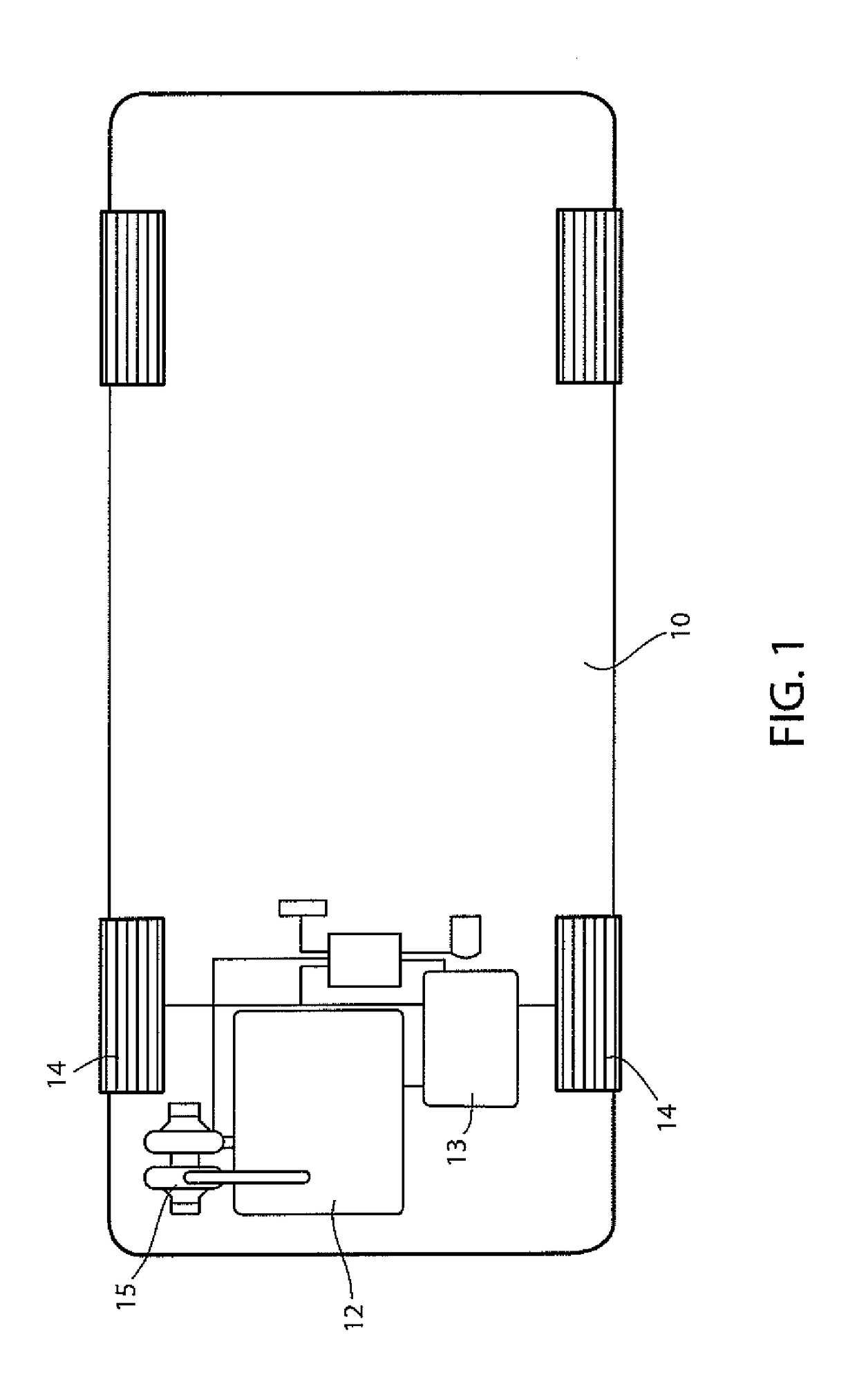
[0016]Shown in FIG. 1 is a schematic illustration of a vehicle 10 having an internal combustion engine 12 mechanically linked to a transmission 13 that drives wheels 14. A turbocharger 15 is provided to increase the efficiency of and / or the power from the engine 12.

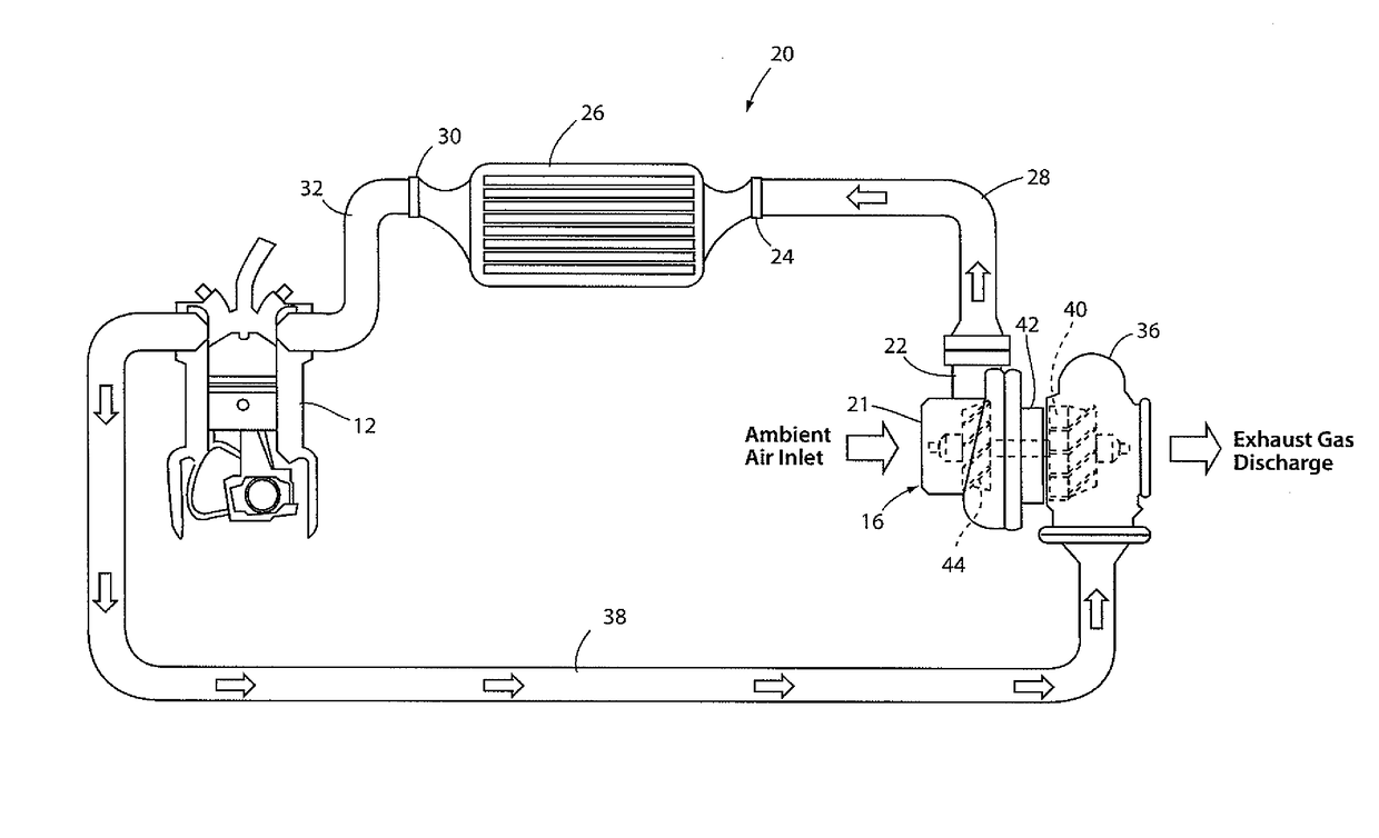
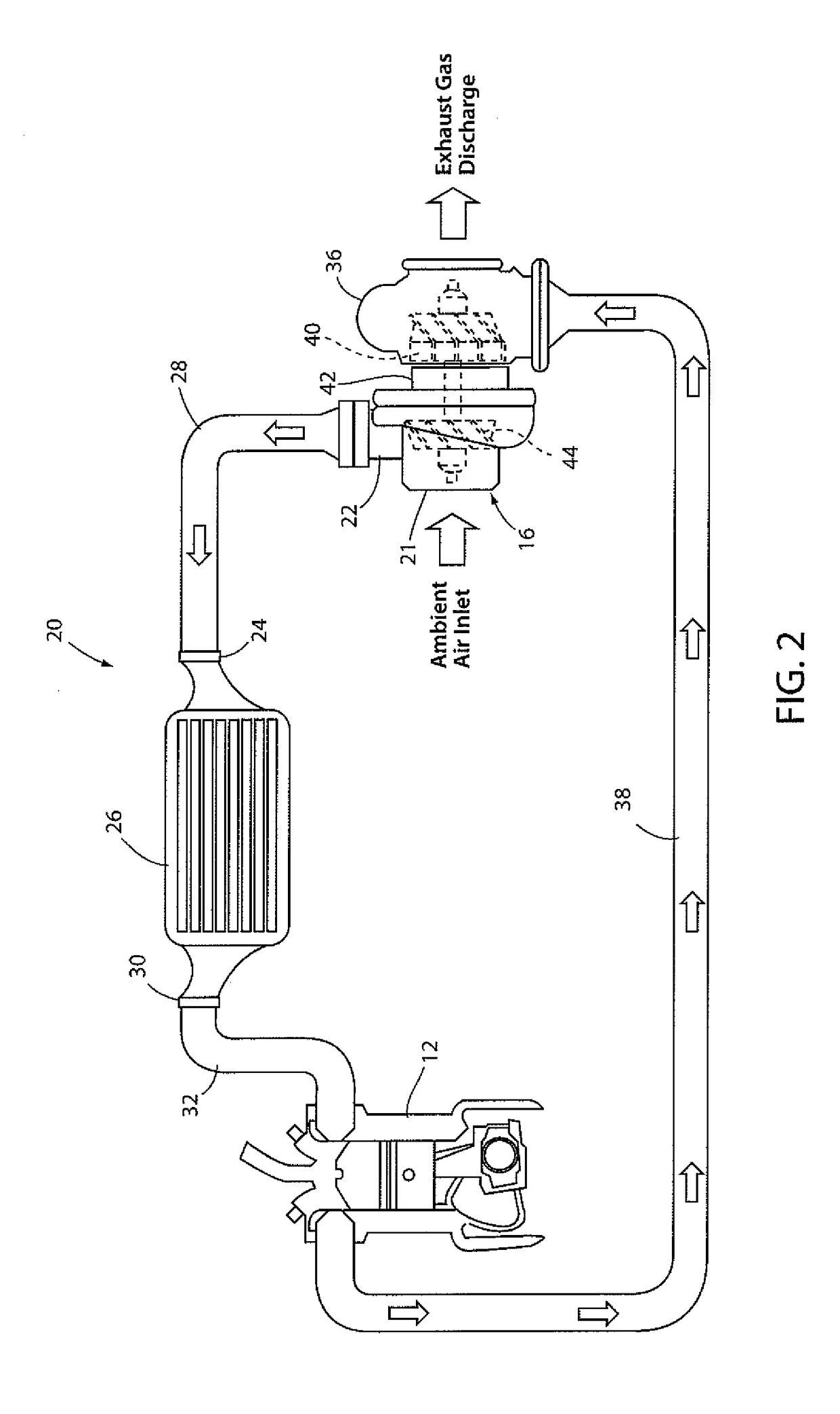
[0017]A turbocharger system 20 is shown in FIG. 2. The system 20 incorporates turbocharger 15 which includes a compressor 16 that draws ambient air into inlet 21 and discharges compressed air from discharge outlet 22. The compressed air from discharge outlet 22 is conveyed to an air cooler inlet port 24 of an air cooler 26 via pipe 28. Air flows over fins of the cooler 26 as the vehicle moves, cooling the compressed air before it exits cooler 26 from cooler outlet port 30 and is conveyed to an air intake manifold of engine 12 via pipe 32. Combustion products exhausted from engine 12 flow to a turbine 36 via a pipe 38. The exhaust gases cause rotation of a turbine wheel 40 that is connected with a shaft 42 that drives a co...


PUM


Abstract

A turbocharger compressor housing is configured to allow a releasable fixed adjustment of a geometry of a compressor housing to increase at least one of responsiveness, efficiency or the ultimate power obtainable by a turbocharged system. Adjustability can be provided by an air intake pipe that is threadably connected with a central portion of the compressor housing to allow an air gap between the housing and the intake pipe to be adjusted to create an effect similar to adjusting the inducer area of a compressor wheel disposed in the housing, whereby power can be exchanged for efficiency and responsiveness. Set screws may be used to releasably fix the position of the intake pipe relative to the compressor housing.

Description

CROSS-REFERENCE TO RELATED APPLICATIONS[0001]Not applicable.FIELD OF THE DISCLOSURE[0002]This disclosure relates to turbochargers, and more particularly to a turbocharger having a compressor housing that has an adjustable geometry to allow the turbocharger compressor to be tuned to a particular application.BACKGROUND OF THE DISCLOSURE[0003]Turbochargers are used in conjunction with internal combustion engines in vehicles (e.g., trucks, automobiles, tractors, etc.) to increase power output, improve efficiency, lower emissions or to achieve a combination of these advantages or improvements. A turbocharger is comprised of a turbine that converts kinetic energy in the combustion products exhausted from the engine into mechanical work that is transmitted to a compressor that draws in ambient air and discharges the air at a higher pressure. The higher pressure air discharged from the turbocharger compressor is conveyed to the air intake manifold of the internal combustion engine, providin...

Claims


Application Information

Patent Timeline
Patent Type & Authority Patents(United States)
IPC IPC(8): F02B33/44F02B37/12F02C6/12F04D27/02F04D29/46F04D29/42
CPCF02B37/12F02C6/12F04D27/0253F04D29/464F04D29/4213Y02T10/144F05D2220/40F05D2250/51Y02T10/12
Inventor DEVINE, WILLIAM
Owner BULLSEYE POWER
Learn More