Swash plate compressor having a curved piston guide wall

a technology of swash plate compressor and guide wall, which is applied in the direction of pump components, positive displacement liquid engines, machines/engines, etc., can solve the problems of high mechanical load on the guiding part of the piston pump and increase the production cost of the piston pump, so as to increase the mechanical and thermal load capacity of the guiding part and reduce the amount of material used for the base. , the effect of high mechanical stability

Active Publication Date: 2018-04-03
ALFRED KARCHER GMBH & CO KG
View PDF16 Cites 0 Cited by
  • Summary
  • Abstract
  • Description
  • Claims
  • Application Information

AI Technical Summary

Benefits of technology

[0008]In the piston pump according to the invention, a piston guiding part having a curved supporting wall is used. Due to the curvature of the supporting wall, on the one hand the mechanical load capacity of the piston guiding part can be significantly increased without the supporting wall requiring reinforcement ribs or a great material thickness for this purpose. On the other hand, due to the curved shape of the supporting wall, its surface area is increased so that the supporting wall also has improved thermal load capacity since due to the greater surface area, reliable heat dissipation is ensured without necessarily having to provide cooling ribs for the supporting wall. The comparatively low material input required for the supporting wall reduces the weight of the piston guiding part. Moreover, the piston guiding part having the curved supporting wall can be produced in a cost-effective manner so that the production costs of the piston pump can be reduced.
[0019]Particularly high mechanical stability is achieved in a preferred embodiment of the invention in that a cylindrical collar is formed on the outer circumference of the supporting wall. In a preferred configuration, the cylindrical collar engages into a cylindrical housing of a wobble plate.

Problems solved by technology

The piston guiding part is subjected to high mechanical load.
This results in increased production costs for the piston pump.

Method used


Image

  • Swash plate compressor having a curved piston guide wall
  • Swash plate compressor having a curved piston guide wall
  • Swash plate compressor having a curved piston guide wall

Examples


Embodiment Construction

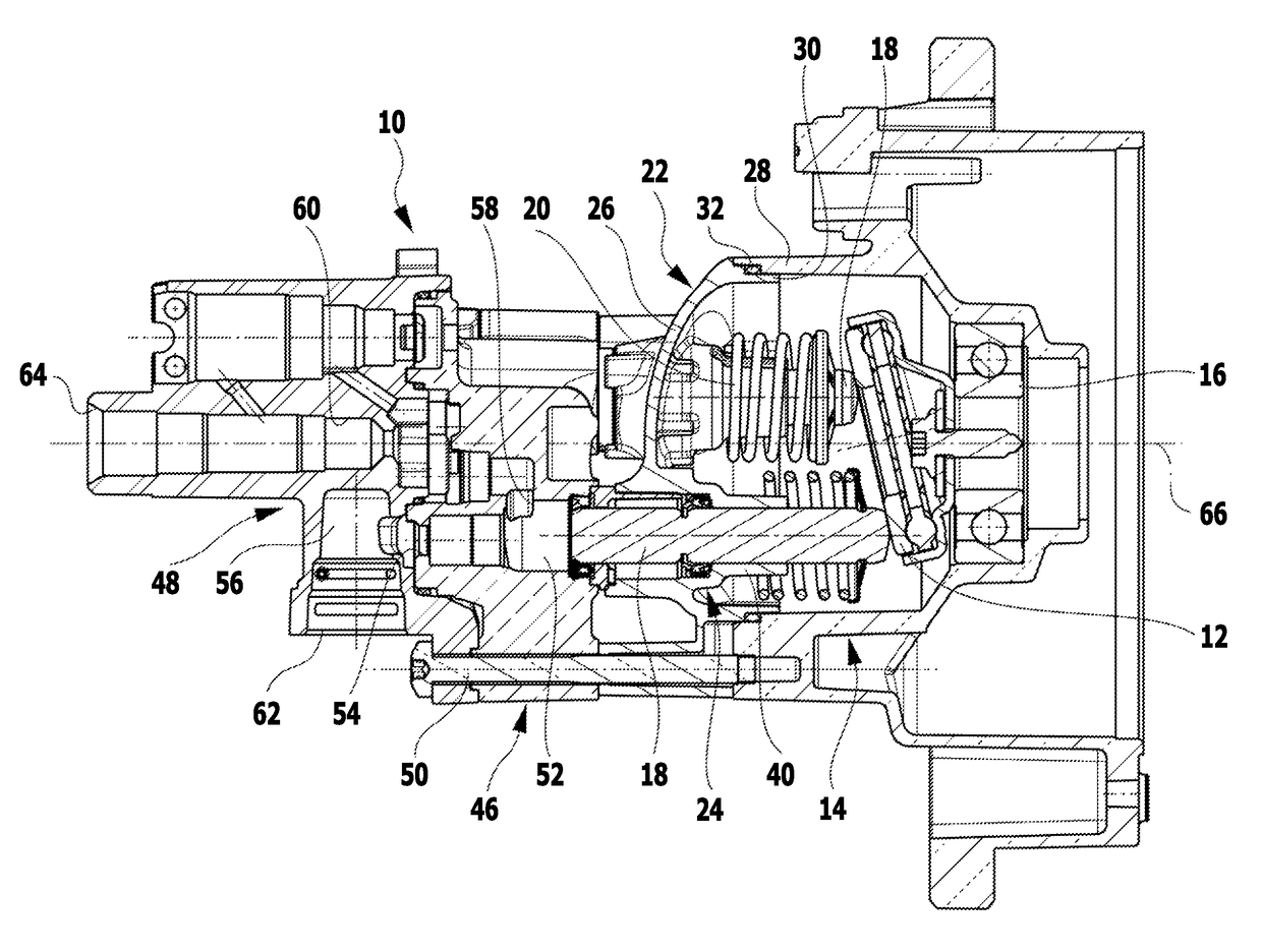
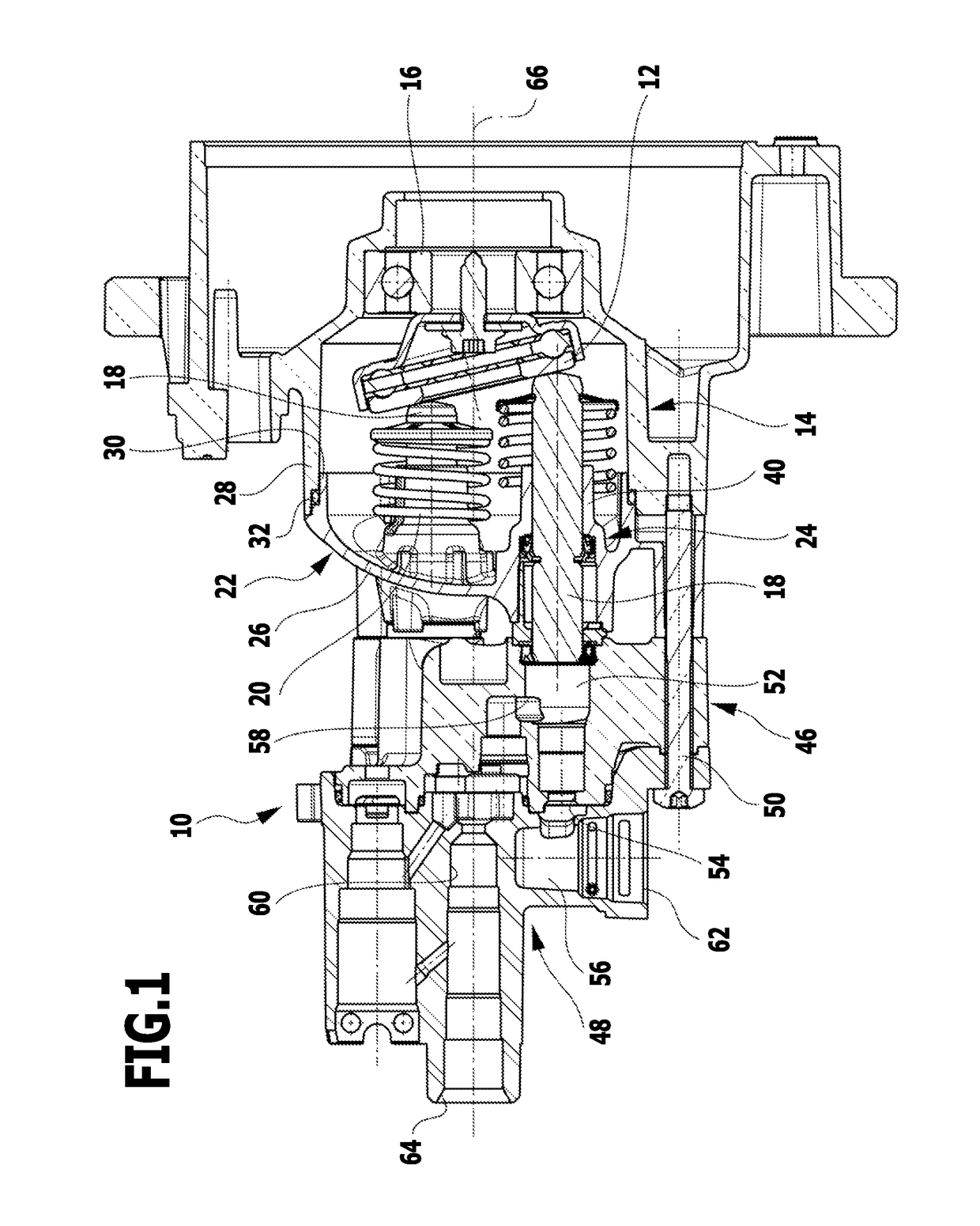
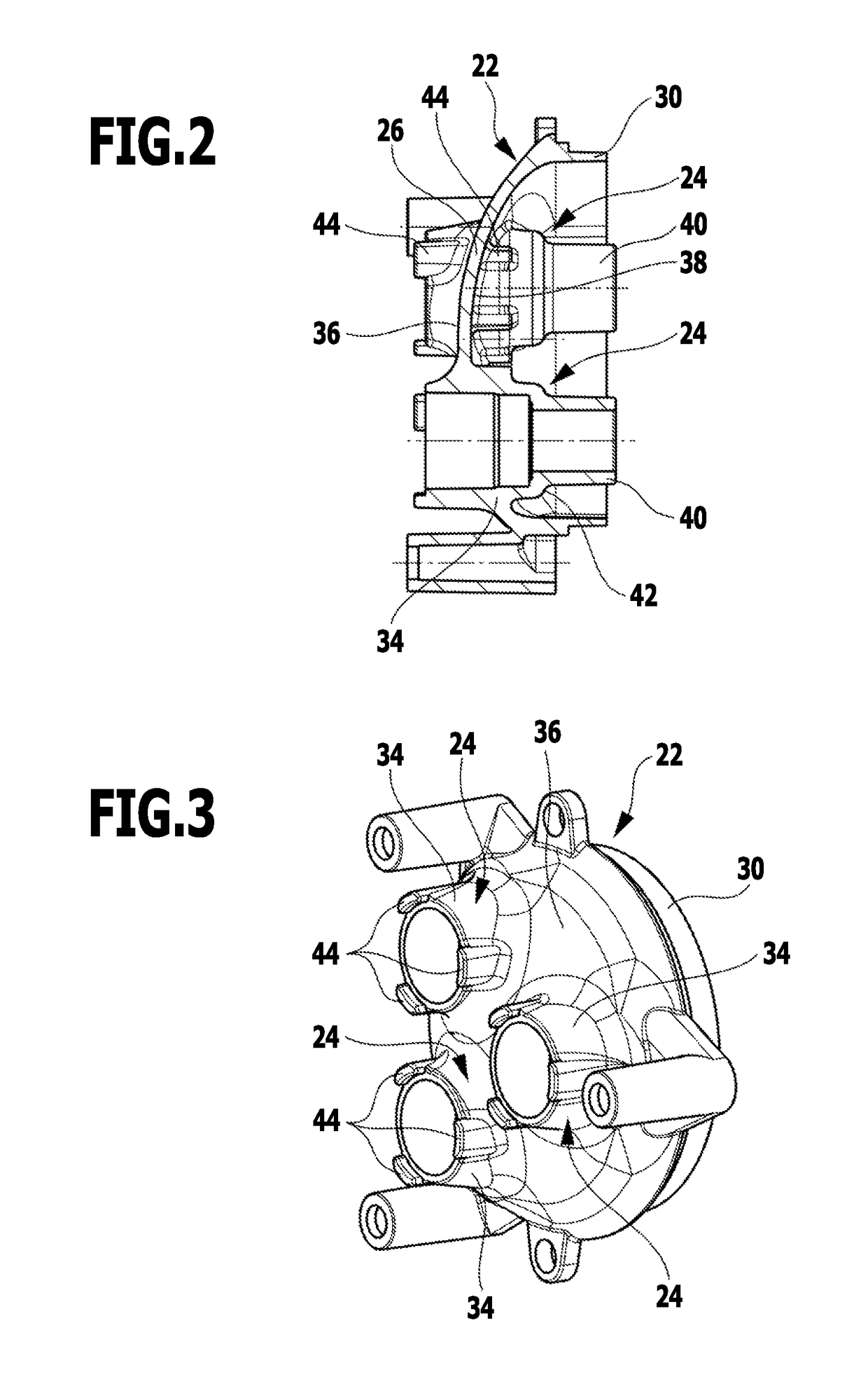
[0029]FIGS. 1 to 4 schematically illustrate a first embodiment of a piston pump according to the invention, which as a whole is designated by reference number 10. The piston pump can be attached in a customary manner to a motor, not shown in the drawing, which rotationally drives a wobble plate 12 that is rotatably mounted in a wobble plate housing 14 by means of a ball bearing 16. The piston pump 10 comprises a plurality of identically configured pistons 18 that rest against the front side of the wobble plate 12 facing away from the ball bearing 16, and are pressed toward the wobble plate 12 by means of return springs 20. The pistons 18 are held at a piston guiding part 22 of the piston pump 10 in a linearly displaceable manner. For this purpose, the piston guiding part 22 has guiding elements 24, each of which guides a piston 18 and is integrally connected to a supporting wall 26 of the piston guiding part 22.

[0030]The supporting wall 26 is configured in the manner of a spherical ...


PUM


Abstract

A piston pump for a high-pressure cleaning appliance is provided, which includes a plurality of pistons that are movable back and forth and each of which enters a pump chamber and is displaceably held at a piston guiding part. The piston guiding part has a supporting wall on which a plurality of guiding elements, each of which guides a piston, are disposed. In order to be able to produce the piston pump in a more cost-effective manner, it is proposed according to the invention that the supporting wall is curved.

Description

CROSS-REFERENCE TO RELATED APPLICATIONS[0001]The present application is a continuation of international application No. PCT / EP2012 / 069867, filed on Oct. 8, 2012, which claims the benefit of German application No. 10 2011 054 442.9, filed on Oct. 12, 2011, the entire specification of both being incorporated herein by reference.BACKGROUND OF THE INVENTION[0002]The invention relates to a piston pump for a high-pressure cleaning appliance, comprising a plurality of pistons that are movable back and forth and each of which enters a pump chamber and is displaceably held at a piston guiding part, the piston guiding part having a supporting wall on which a plurality of guiding elements, each of which guides a piston, are disposed.[0003]Piston pumps of this kind are known, for example, from DE 39 18 022 C2. By means of such a piston pump, a liquid, preferably water, can be drawn in, pressurized and subsequently discharged. For this purpose, the pump chamber is connected via a suction valve t...

Claims


Application Information

Patent Timeline
Patent Type & Authority Patents(United States)
IPC IPC(8): F04B1/14F04B27/10F04B39/12
CPCF04B1/145F04B39/122F04B27/1081F04B1/143
Inventor HOFER, THOMAS
Owner ALFRED KARCHER GMBH & CO KG
Why Eureka
Try Eureka