
Optimizing performance of a drilling assembly
a technology of drilling assembly and drilling performance, which is applied in the direction of adaptive control, borehole/well accessories, instruments, etc., can solve the problems of limiting this relationship, affecting the performance of drilling assembly, and rop generally increasing substantially linearly, so as to achieve continuous optimization of drilling performance and optimize drilling performance.
- Summary
- Abstract
- Description
- Claims
- Application Information
AI Technical Summary
Benefits of technology
Problems solved by technology
Method used
Image

Examples
Embodiment Construction
The System: Self-Tuning Multivariable Controller
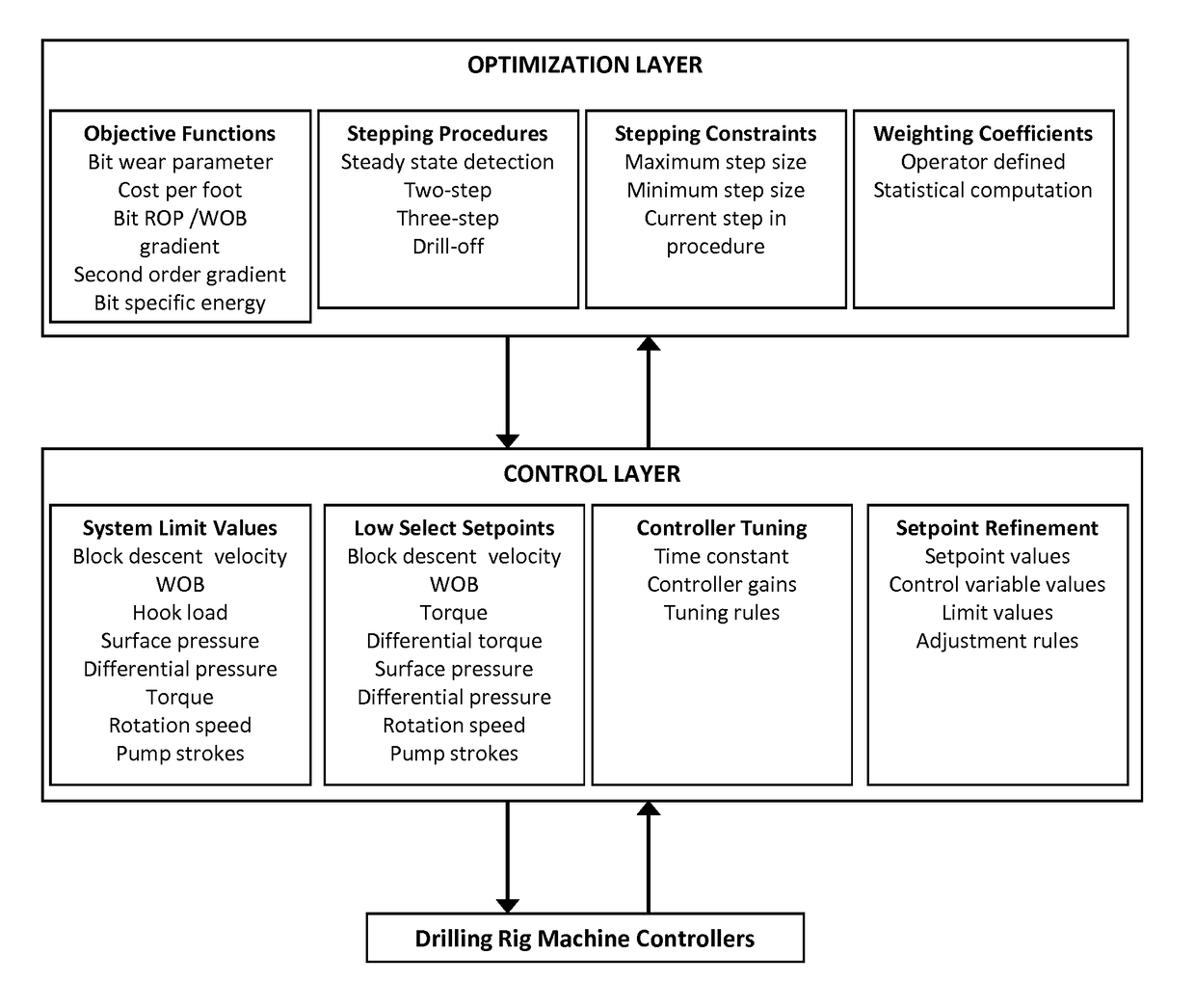
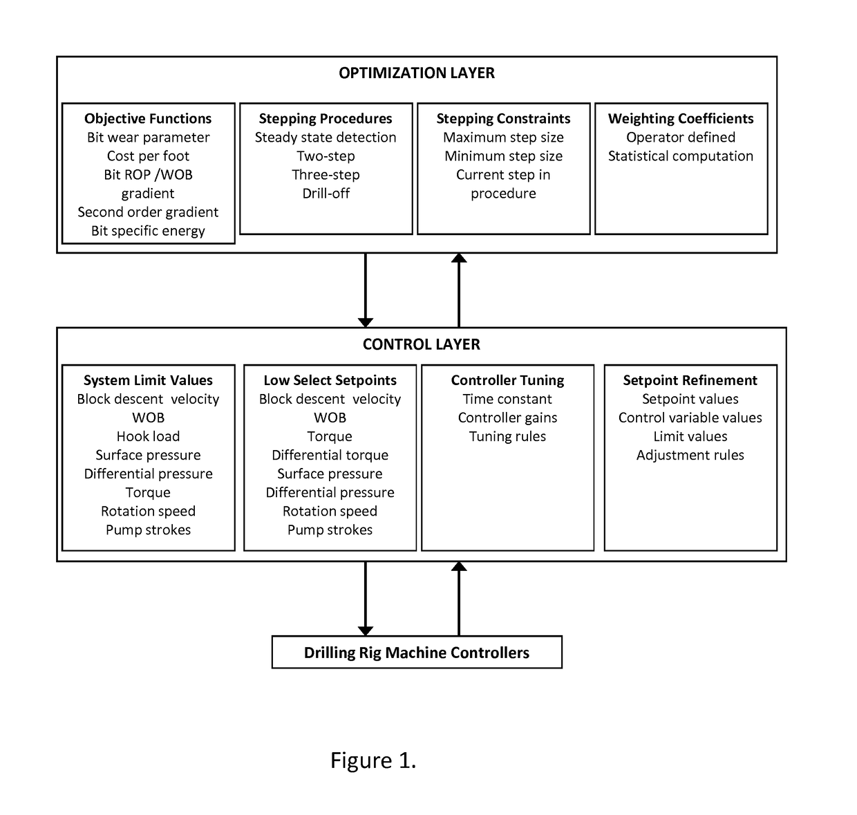
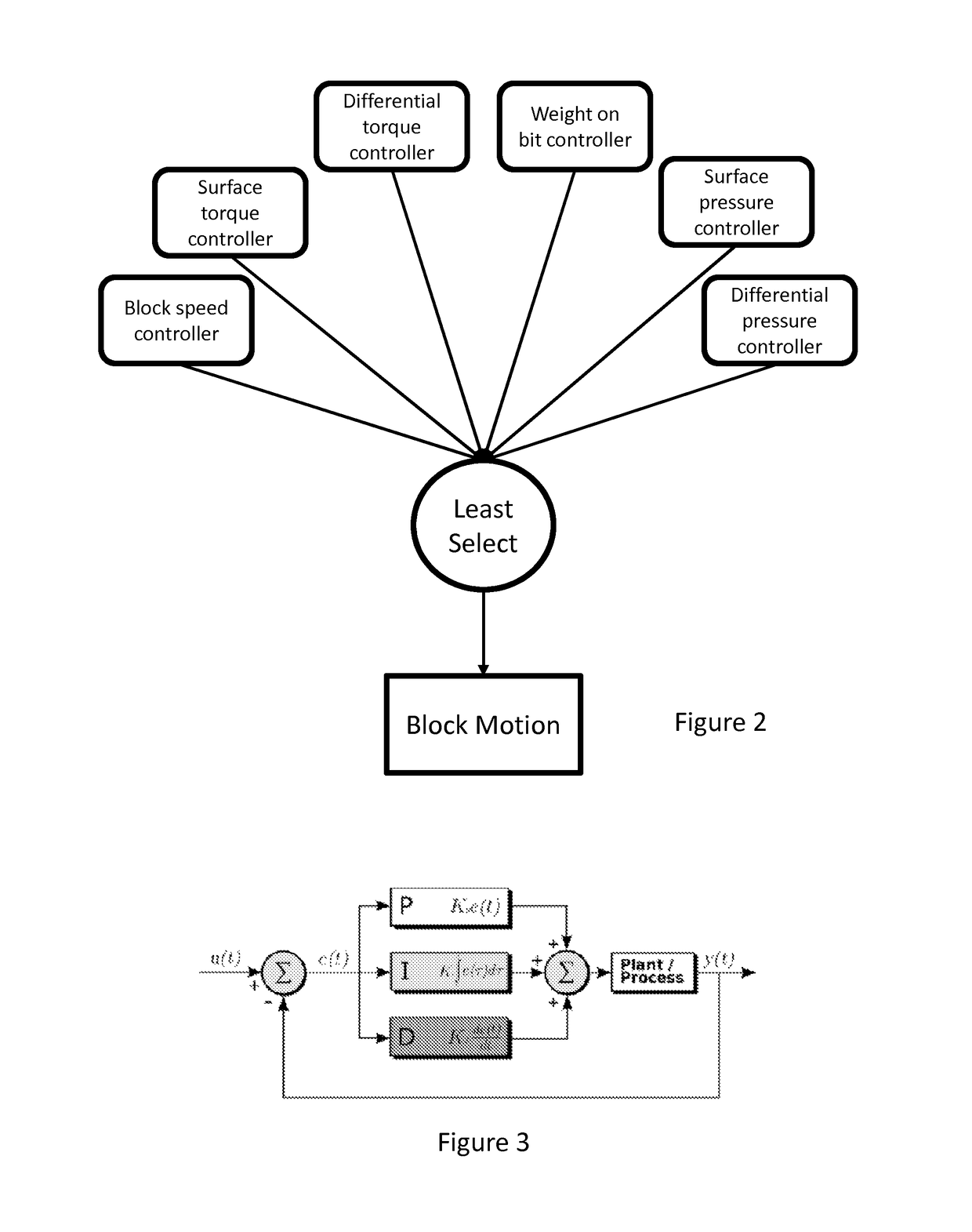
[0044]FIG. 1 presents a structural view of the drilling control and optimization system. The control layer comprises a self-tuning, multivariable controller that enables improved, simultaneous maintenance of desired setpoints for a number of drilling variables. FIG. 2 provides examples of variables that can be used as the basis for control. In a preferred embodiment, the controllers for each of these variables are of the proportional-integral-derivative (PID) type, a block diagram of which is provided in FIG. 3. The standard form of the governing equation for a PID controller is provided below.
[0045]z=KCe+KCTI∫0tedτ+KCTDe.(1)
[0046]In the above equation z is the controller output, e is the error (defined as the setpoint minus the process variable value at the current time), KC is the controller gain, alternately known as the proportional gain, and TI and TD are time constants for integral and derivative terms, respectively. The...
PUM
 Abstract
Description
Claims
Application Information