Heat spreading module

a technology of heat spreading module and heat dissipation function, which is applied in the direction of indirect heat exchangers, light and heating apparatuses, laminated elements, etc., can solve the problems of deterioration of heat dissipation function, inability to select the amount of heat transfer or heat transfer path, and increase the amount of heat transfer. , the effect of large heat transfer capacity

Inactive Publication Date: 2018-04-10
THE FUJIKURA CABLE WORKS LTD
View PDF18 Cites 2 Cited by
  • Summary
  • Abstract
  • Description
  • Claims
  • Application Information

AI Technical Summary

Benefits of technology

[0009]The present invention has been made in view of the circumstances described above, and provides a heat spreading module capable of promoting heat dissipation by positively transferring heat, which is transferred to a heating portion, to a heat radiation portion and capable of being thinner.
[0014]According to the aspects of the present invention described above, heat transferred to a heating portion is dissipated over an entire main body by thermal conduction of the main body, and a working fluid evaporates in each hollow path. The vapor flows in the hollow path toward a portion having a low pressure due to a low temperature, and is thereby transported by the working fluid in a longitudinal direction of the hollow path and is dissipated. The transportation of heat by the working fluid is transportation as latent heat of the working fluid, and a larger amount of heat is transported than in thermal conduction of the main body. Therefore, the present invention has excellent heat dissipation performance. In addition, the transportation amount of heat or the dissipation amount thereof in a portion in which the hollow path is formed is larger than that in a portion in which the hollow path is not formed. Therefore, by disposing the hollow path in a portion having a large amount of heat radiation, a large heat capacity for cooling, or the like, it is possible to increase the amount of heat transfer from the heating portion and to further improve heat dissipation performance or heat radiation performance.
[0015]According to the aspects of the present invention described above, the hollow paths communicate with each other in the heating portion, and a part of each wick is disposed in the heating portion. Therefore, in each hollow path, the whole working fluid in a liquid phase flows back to the heating portion. Therefore, the total amount of the working fluid evaporates and condenses without waste to transport heat. When heat is not easily transported in any one of the plurality of hollow paths, a working fluid in the hollow path flows into another hollow path to be used for heat transportation. Also in this point, the working fluid transports heat without waste. As a result, by communication of the hollow paths with each other in the heating portion and disposition of a part of each wick in the heating portion, heat dissipation performance can be improved more than ever.

Problems solved by technology

Therefore, a heat dissipation function is deteriorated and the temperature of a heat spot is raised with reduction in thickness of the graphite sheet.
That is, in the structure, the amount of heat transfer or a path for heat transfer cannot be selected.
Therefore, even when there is a portion effective for cooling an integrated circuit such as a portion having a low temperature and a large heat capacity, for example, heat transfer to the portion cannot be promoted.

Method used


Image

  • Heat spreading module
  • Heat spreading module
  • Heat spreading module

Examples


Embodiment Construction

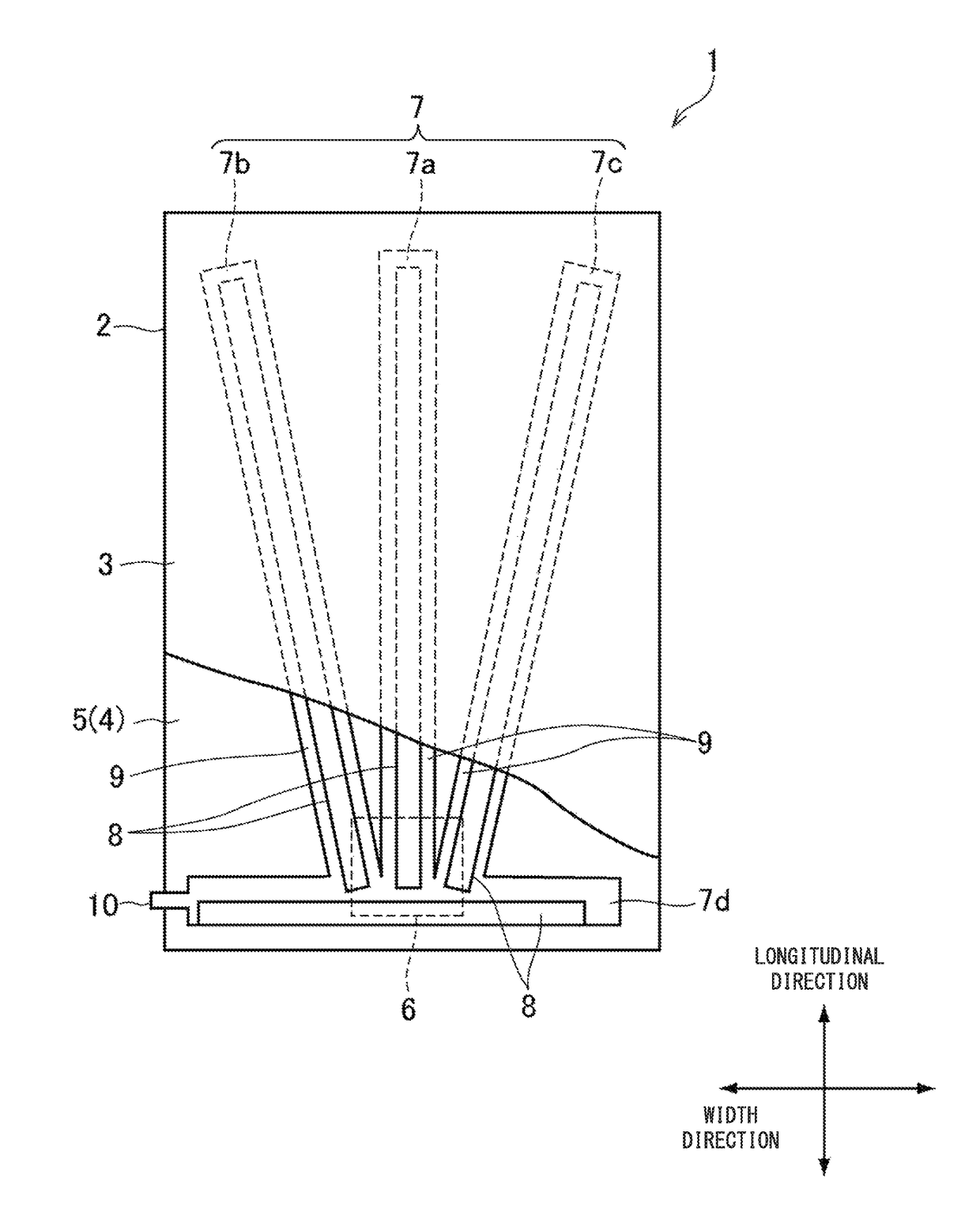
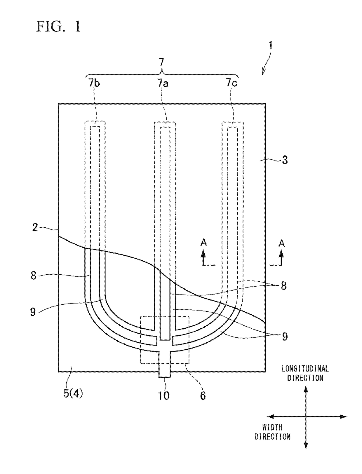
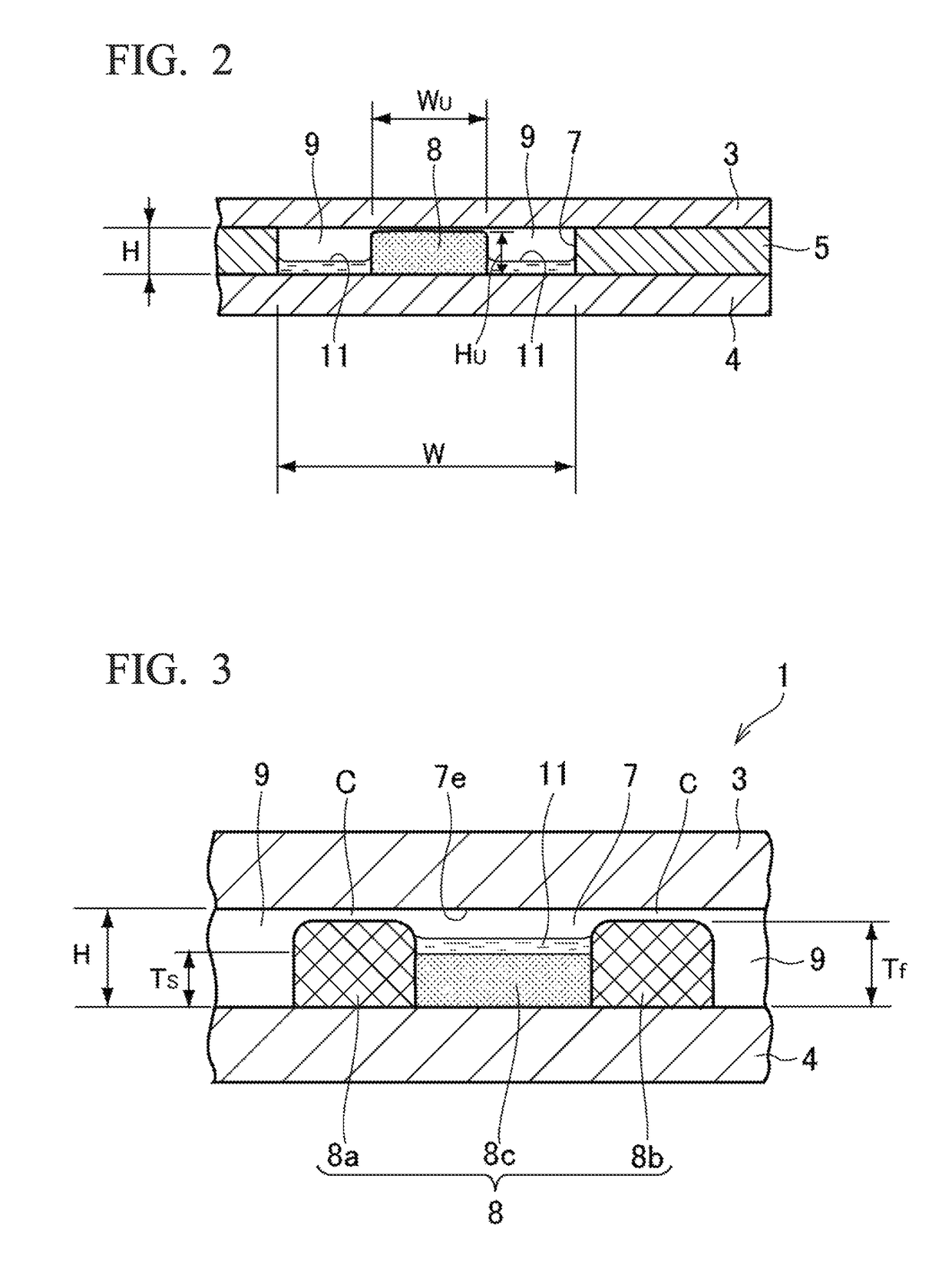
[0020]FIG. 1 is a plan view exemplifying a heat dissipation plate (heat spreading module) 1 according to an embodiment of the present invention. FIG. 2 is a cross sectional view cut along line A-A in FIG. 1. The heat dissipation plate 1 includes a main body 2 formed into a thin rectangular plate shape. The main body 2 includes an upper plate 3, a lower plate 4, and a middle plate 5 each of which is a metal plate. Among these plates 3, 4, and 5, at least the upper plate 3 and the lower plate 4 are formed of a clad material integrated by laminating a stainless steel plate, an aluminum plate, or an aluminum alloy plate and copper plates disposed on a front surface and a back surface thereof. The middle plate 5 is preferably formed of a copper plate. The upper plate 3 and the middle plate 5 are bonded to each other and the middle plate 5 and the lower plate 4 are bonded to each other in an airtight state by an appropriate method. A preferable example of the bonding method is dissipation...


PUM


Abstract

In a heat spreading module, a plurality of hollow paths is formed in a thin plate-shaped main body so as to pass though the heating portion, and the hollow paths communicate with each other in a heating portion, a working fluid is enclosed in the hollow paths, a wick is disposed in each of the hollow paths such that a vapor flow path in which vapor of the working fluid flows is formed in each of the hollow paths, a part of each wick is positioned at the heating portion, and the vapor flow paths formed in the hollow paths communicate with each other in the heating portion.

Description

CROSS REFERENCE TO RELATED APPLICATIONS[0001]The present application claims priority with respect to Japanese patent application No. 2015-109384 filed on May 29, 2015, the contents of which are incorporated herein by reference.BACKGROUND[0002]Technical Field[0003]The present invention relates to a heat spreading module suitable for dissipating heat of an electronic element which is a heat-generating body in a portable information terminal such as a smartphone or a tablet personal computer or an electronic device.[0004]Description of the Related Art[0005]In a portable information terminal or an electronic device, the amount of heat generation is increasing with increase in the amount of information processing, and need for suppressing rise in the temperature of an electronic element such as CPU is increasing in order to prevent malfunction due to heat, reduction in an information processing speed, or the like. Furthermore, in the portable electronic device, thickness reduction, weigh...

Claims


Application Information

Patent Timeline
Patent Type & Authority Patents(United States)
IPC IPC(8): F28D15/00F28D15/02F28D15/04F28F3/08F28F21/08F28D21/00
CPCF28D15/0266F28D15/0258F28D15/0283F28D15/046F28F21/083F28F21/084F28F21/085F28F21/089F28F3/08F28D2021/0028F28D15/0233
Inventor PHAN, THANHLONGKAWAHARA, YOUJIYOKOYAMA, YUICHISAITO, YUJIAHAMED, MOHAMMAD SHAHEDMASHIKO, KOICHI
Owner THE FUJIKURA CABLE WORKS LTD
Why Eureka
Try Eureka