System and method for sensorless control of electric machines using magnetic alignment signatures

a sensorless control and electric machine technology, applied in the field of electric machines, can solve the problems of sensorless control, reduced back-emf magnitude, and significant portion of the cost and overall complexity of the motor drive system

Active Publication Date: 2018-04-17
GENERAL ELECTRIC CO
View PDF36 Cites 27 Cited by
  • Summary
  • Abstract
  • Description
  • Claims
  • Application Information

AI Technical Summary

Benefits of technology

[0011]In accordance with yet another aspect of the invention, a drive system for use with an AC electric machine not having suitable sensitivity for saliency tracking sensorless control is provided. The drive system is configured to generate a primary excitation current vector to drive the AC electric machine, the primary excitation current vector having a current magnitude and current angle. The drive system is also configured to inject a carrier signal onto the primary excitation current vector, the carrier signal comprising one of a carrier voltage and a carrier current that is superimposed on the primary excitation current vector. The drive system is further configured to measure at least one magnetic alignment signature of the AC electric machine that is derived from a carrier response signal generated from the injected carrier signal and control an orientation of the primary excitation current vector using the measured at least one magnetic alignment signature, so as to achieve a desired magnetic operation of the AC electric machine.

Problems solved by technology

It is recognized, however, that the position sensor (e.g., encoder), along with its cabling and interface electronics, contributes to a significant portion of the motor drive system cost and overall complexity and is often a major reliability concern.
The cost, complexity, and reliability issues associated with the use of position sensors in determining rotor position has led to the advent of systems and methods of sensorless position sensing and control of electric machines (i.e., not requiring rotor position or speed sensors).
Because of the tremendous potential of cost reduction and reliability improvement, sensorless control has been a major research challenge.
However, as the speed is reduced, the back-EMF magnitude is reduced and performance is deteriorated.
Eventually, as the speed is close to zero, these methods become unstable and fail, because the back-EMF diminishes and becomes unobservable.
This limits back-EMF tracking methods to HVAC type of applications where open-loop starting is acceptable.
However, with respect to previously employed encoderless controls that employ high frequency injection, it is recognized such encoderless controls have failed to find success in recovering the full, or near full, torque capability of the machine due to the loss of small signal saliency at high-load levels for the machine, this being due to magnetic saturation at such high-load levels.
Moreover, a cross saturation effect causes the saliency angle to shift away from the d-axis, causing position estimation angle error even though the q-axis small signal inductance is still larger than d-axis.
Therefore, existing high frequency injection methods have been limited to applications where torque density requirement is low and also the dynamic performance requirement is modest.
Especially, for such applications as traction drives where very high torque density is desired, existing sensorless control methods could achieve only a small fraction of the desired torque requirement, let alone the dynamic performance.
While the inclusion of such a special rotor structure or D-ring has enabled increased torque control of an electric machine via the use of high frequency injection sensorless controls, it is recognized that inclusion of such a D-ring in the electric motor may still not provide for full sensorless control of an electric machine, as even with a D-ring it is difficult to maintain a desired level of saliency during operation of the machine due to the severe saturation at very high torque level.

Method used


Image

  • System and method for sensorless control of electric machines using magnetic alignment signatures
  • System and method for sensorless control of electric machines using magnetic alignment signatures
  • System and method for sensorless control of electric machines using magnetic alignment signatures

Examples


Embodiment Construction

[0040]For purposes of better understanding the descriptions set forth herebelow, the following listing of the nomenclature and abbreviations which will be used is provided.

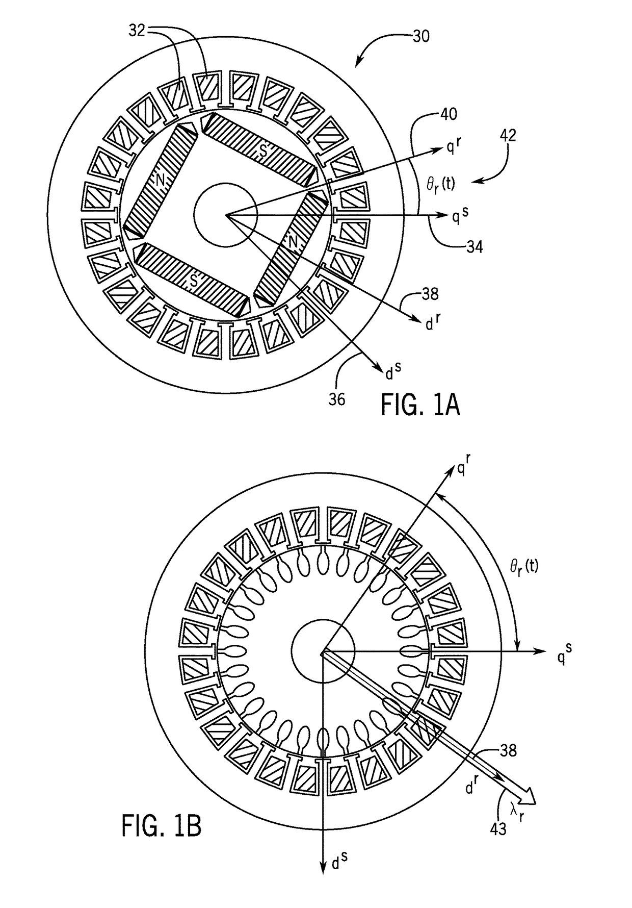
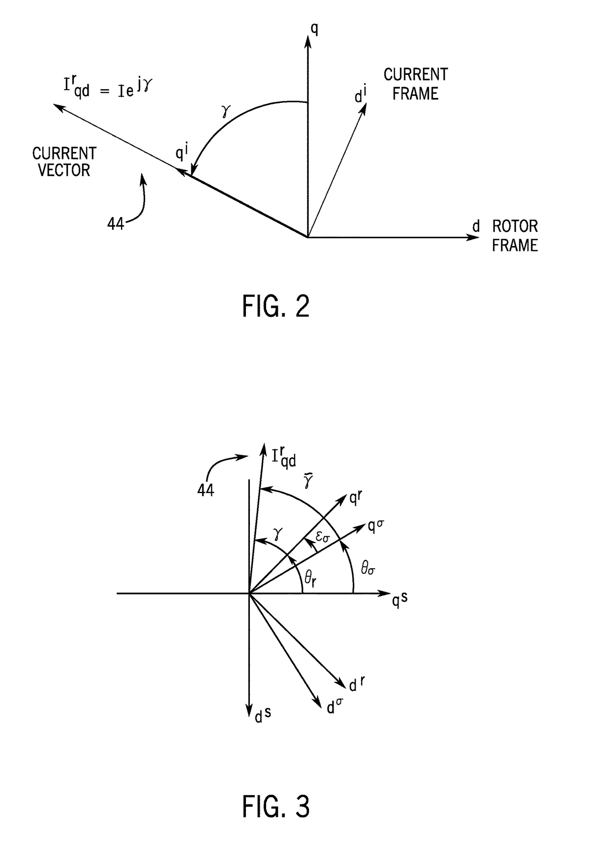
[0041]Reference frame unit vectors for AC machines[0042]qs stationary frame quadrature axis; aligned with a-phase in general[0043]ds stationary frame direct axis;[0044]qr, q rotor synchronous frame quadrature axis[0045]dr, d rotor synchronous frame direct axis[0046]qi current frame quadrature axis[0047]di current frame quadrature axis[0048]q quadrature axis of the specified reference frame (rotor frame if not specified)[0049]d quadrature axis of the specified reference frame (rotor frame if not specified)

Complex Vectors for AC Machine Variables (and Vector Generalization)[0050]f bold characters used for complex vectors and complex coefficients bold characters used for vectors and matrices[0051]fqd=fq−j·fd complex vector representation for ac machine variables[0052]fqd=[fq fd]T 2D vector representation of a complex...


PUM


Abstract

A system and method for position sensorless control of an AC electric machine is disclosed. A drive system for driving an AC electric machine provides a primary current excitation to drive the AC electric machine, the primary current excitation comprising a current vector having a magnitude and angle. The drive system injects a carrier signal to the AC electric machine that is superimposed onto the current vector, with the carrier signal being selected to generate a carrier response signal that has sensitivity to magnetic alignment information of the AC electric machine at its operating point. The drive system measures at least one magnetic alignment signature of the AC electric machine from the generated carrier response signal and controls an orientation of the current vector using the measured at least one magnetic alignment signature, so as to achieve a desired magnetic operation of the AC electric machine.

Description

BACKGROUND OF THE INVENTION[0001]Embodiments of the invention relate generally to electric machines and, more particularly, to a sensorless method for controlling an electric machine via the use of signatures that are produced by the saturation behavior of the electric machine dependent on an alignment of excitation current provided to the stator thereof.[0002]The usage of electric machines in various industries has continued to become more prevalent in numerous industrial, commercial, and transportation industries over time. With an electric machine, be it an interior electric machine (IPM) machine, permanent magnet (PM) assisted synchronous reluctance machine, or a synchronous reluctance machine, position determination of the rotor or the magnetic field is a critical informational element for torque control of the machine.[0003]For purposes of determining rotor position in an electric machine, an encoder, tachometer, or resolver may be used as the position sensor. For measuring th...

Claims


Application Information

Patent Timeline
Patent Type & Authority Patents(United States)
IPC IPC(8): H02P21/00H02P21/24H02P6/18H02P21/18H02P27/08
CPCH02P21/24H02P27/08H02P21/18H02P6/183H02P25/024H02P23/14H02P25/08H02P27/12H02P2203/09H02P2205/05H02P2205/01H02P21/26H02P25/089H02P25/022
Inventor HUH, KUM-KANGPAN, DI
Owner GENERAL ELECTRIC CO
Why Eureka
Try Eureka