Dosimetric scintillating screen detector for charged particle radiotherapy quality assurance (QA)

a detector and charged particle technology, applied in the field of quality assurance of particle therapy, can solve the problems of inability to make an array, inability to detect current particles, and inability to meet the spatial characteristics of the beam of penetrating radiation,

Active Publication Date: 2018-05-01
EBSTEIN STEVEN M
View PDF10 Cites 1 Cited by
  • Summary
  • Abstract
  • Description
  • Claims
  • Application Information

AI Technical Summary

Problems solved by technology

In practice, current detectors fall short in one or more respects.
However, their detection signal is not linear with the fluence or LET of the radiation beam, which is required in order to predict the corresponding dose to the patient.
However, scintillator light output is generally not linear with the LET of the incident particles.
However, due to their size and complexity, they cannot be made into arrays that can measure the incident radiation distribution with the required resolution.
Due to the limitations of these detectors, a complex system is required to perform and evaluate the QA measurements.
Typically, a series of representative measurements are made with detectors that have high spatial resolution but poor dosimetric accuracy or detectors with limited spatial resolution but good dosimetric accuracy.
However, this approach cannot give complete confidence that the delivered beam matches the plan due to reduced dimensionality of the measurements.
In addition, the work required to construct the models and perform the calculations of the expected measurements adds to the cost and complexity of performing QA.
The beam delivery systems are complex instruments and are required to produce a series of beams with complex shapes and different energy spectra.
Current detectors and systems cannot directly measure the delivered dose as a function of depth with sufficient accuracy or spatial resolution to quickly and easily perform the QA task.

Method used


Image

  • Dosimetric scintillating screen detector for charged particle radiotherapy quality assurance (QA)
  • Dosimetric scintillating screen detector for charged particle radiotherapy quality assurance (QA)
  • Dosimetric scintillating screen detector for charged particle radiotherapy quality assurance (QA)

Examples


Embodiment Construction

[0057]In accordance with preferred embodiments of the present invention, the spatial distribution of a beam of penetrating radiation is imaged with a scintillator. The term “penetrating radiation,” as used herein, and in any appended claims, refers both to particles with mass, such as protons, as well as to photons, i.e., to electromagnetic radiation such as x-rays or gamma rays. Moreover, in the case of massive particles, the particles are typically charged, such as protons or heavier atomic ions, however, neutrons or other electrically neutral particles may also be detected, and their beams imaged within the scope of the present invention.

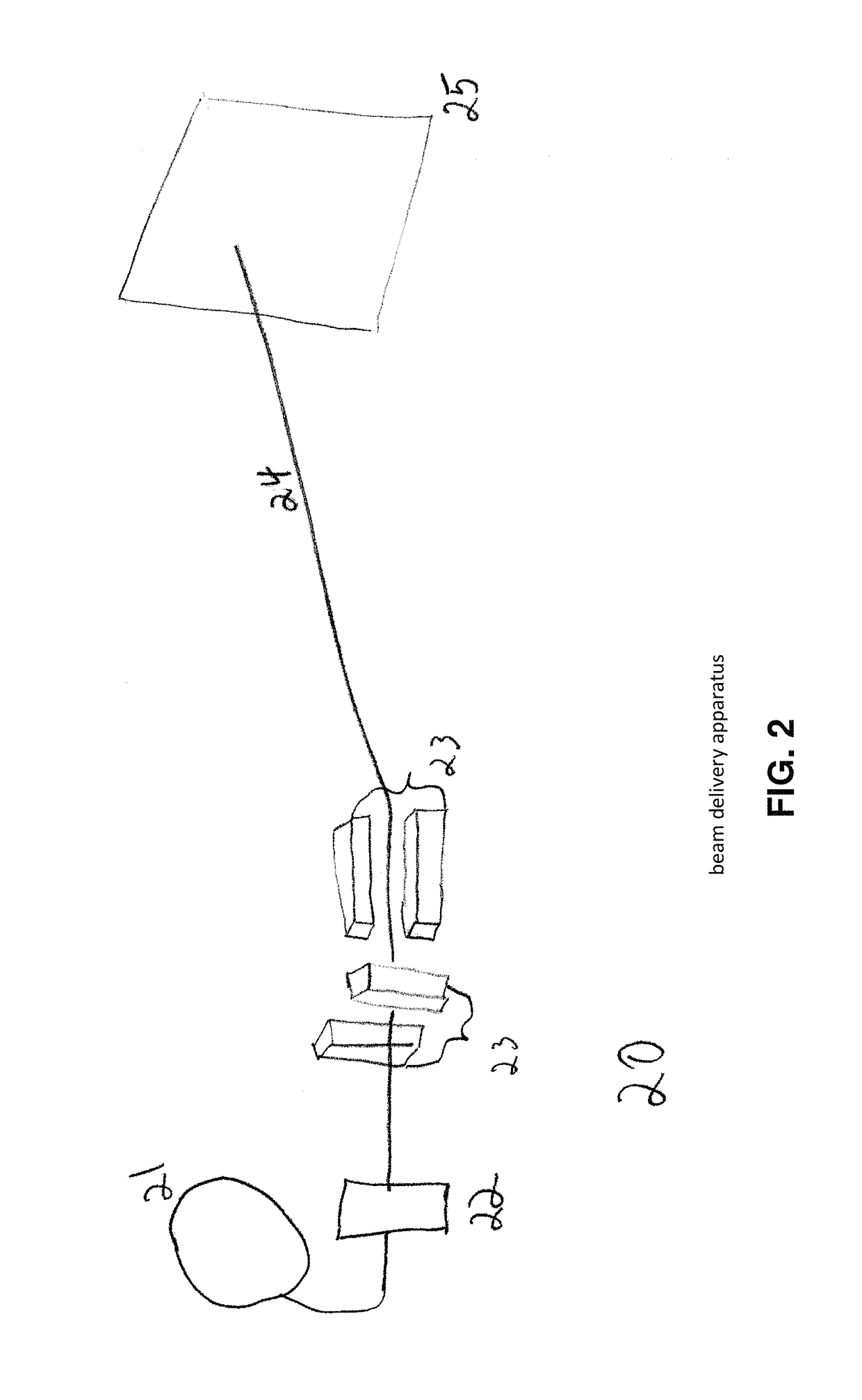
[0058]Referring to FIG. 2, a system for delivering a spatially complex radiation beam is designated generally by 20. The system consists of a radiation source, 21, and a means of setting the energy of the radiation, 22, setting the fluence, and means for shaping the transverse spatial distribution of the radiation, 23. In the case of charged part...


PUM

PropertyMeasurementUnit
diameteraaaaaaaaaa
diameteraaaaaaaaaa
focal lengthaaaaaaaaaa

Abstract

An apparatus and method are provided for performing Quality Assurance of complex beams of penetrating radiation inside a patient. A detector with a transverse scintillating screen images the radiation inside a tissue phantom with high spatial resolution. The scintillator is comprised of a mixture of two or more scintillators emitting different spectra of light and having different characteristic responses as a function of the beam LET value. The optics relaying the scintillation output have variable transmission with wavelength, further shaping the spectrum of light transmitted to the imaging sensor which also has spectrally varying sensitivity. Parameters of the scintillator construction, the optics, and the imaging sensor are chosen so the output of the composite detector is proportional to a characteristic of the input beam, for example the dose deposited as a function of depth inside the tissue phantom.

Description

REFERENCE TO PENDING PRIOR PATENT APPLICATION[0001]This patent application claims benefit of prior U.S. Provisional Patent Application Ser. No. 61 / 602,301, filed Feb. 23, 2012 by Steven M. Ebstein for DOSIMETRIC SCINTILLATING SCREEN DETECTOR FOR CHARGED PARTICLE RADIOTHERAPY QA, which patent application is hereby incorporated herein by reference.FEDERALLY SPONSORED RESEARCH[0002]This invention was made with U.S. Government support under Grant 5R44CA103610-03 awarded by the National Cancer Institute. The U.S. Government has certain rights in the invention.FIELD OF THE INVENTION[0003]The present invention pertains to a device and a method for monitoring the spatial characteristics of a beam of penetrating radiation and, more particularly, to quality assurance in particle therapy, namely, ensuring that the dose delivered matches the intended treatment plan.BACKGROUND OF THE INVENTION[0004]The goal of radiotherapy is to irradiate unhealthy, usually cancerous, tissue or tumors with the a...

Claims


Application Information

Patent Timeline
Patent Type & Authority Patents(United States)
IPC IPC(8): G01J1/00G01N23/04A61N5/10
CPCG01N23/04A61N5/1075A61N2005/1076
Inventor EBSTEIN, STEVEN M.
Owner EBSTEIN STEVEN M
Why Eureka
Try Eureka