Image coding method, image decoding method, image coding apparatus, image decoding apparatus, and image coding and decoding apparatus

a coding method and image technology, applied in the field of image coding method, image decoding method, image coding apparatus, image coding and decoding apparatus, can solve the problems of reducing coding efficiency, inefficient coding of raw luma and chroma samples at a bit-depth larger than the original image samples, and redundancy data of ipcm samples can be reduced, so as to improve coding efficiency. , the effect of improving the quality of the sampl

Active Publication Date: 2018-05-01
SUN PATENT TRUST
View PDF199 Cites 6 Cited by
  • Summary
  • Abstract
  • Description
  • Claims
  • Application Information

AI Technical Summary

Benefits of technology

[0048]According to the present disclosure, it is possible to set a bit-depth for IPCM samples separately and independently from a bit-depth for reconstructed samples. Therefore, redundant data of the IPCM samples can be reduced. As a result, coding efficiency can be improved.

Problems solved by technology

However, one problem is that the signaled bit-depth can be greater than the original image bit-depth before coding process, by increase of the bit-depth.
For an IPCM block, coding the raw luma and chroma samples at a bit-depth larger than the original image samples is inefficient and reduces coding efficiency.
However, an IPCM block containing the original image samples cannot be stored directly into the memory at a lower bit-depth as there is a problem differentiating an IPCM reconstructed block and a lightly compressed block in memory.
This typically results in error in the inter prediction if a wrong decompression scheme is used for the IPCM constructed image block.
However, since to which standard each of the plurality of the video data to be decoded conform cannot be detected, there is a problem that an appropriate decoding method cannot be selected.
However, when the driving frequency is set higher, there is a problem that the power consumption increases.
However, the problems of increase in the scale of the circuit of the LSI ex500 and increase in the cost arise with the individual use of the signal processing units ex507 that conform to the respective standards.

Method used


Image

  • Image coding method, image decoding method, image coding apparatus, image decoding apparatus, and image coding and decoding apparatus
  • Image coding method, image decoding method, image coding apparatus, image decoding apparatus, and image coding and decoding apparatus
  • Image coding method, image decoding method, image coding apparatus, image decoding apparatus, and image coding and decoding apparatus

Examples


embodiment 1

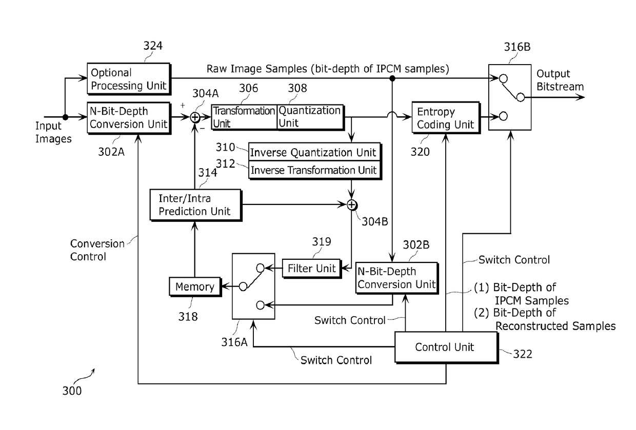
[0099]FIG. 3 is a block diagram which shows a structure of an image coding apparatus according to Embodiment 1 of the present disclosure. The image coding apparatus 300 shown in FIG. 3 is an apparatus for coding an input image bit stream on a block-by-block basis so as to generate a coded output bitstream.

[0100]As shown in FIG. 3, the image coding apparatus 300 includes two N-bit-depth conversion units 302A and 302B, a subtractor 304A and an adder 304B, a transformation unit 306, a quantization unit 308, an inverse quantization unit 310, an inverse transformation unit 312, an inter / intra prediction unit 314, two multiplexers (MUX units) 316A and 316B, a memory 318, a filter unit 319, an entropy coding unit 320, a control unit 322, and an optional processing unit 324.

[0101]Input images are inputted to the N-bit-depth conversion unit 302A and the optional processing unit 324. After the input image bit stream is inputted to the N-bit-depth conversion unit 302A, the N-bit-depth conversi...

embodiment 2

[0127]FIG. 7 is a block diagram which shows a structure of an image decoding apparatus according to Embodiment 2 of the present disclosure. The image decoding apparatus 700 shown in FIG. 7 is an apparatus for decoding an input coded bitstream on a block-by-block basis and outputting images.

[0128]The image decoding apparatus 700 includes as shown in FIG. 7, a demultiplexer (DEMUX unit) 702A, a multiplexer (MUX unit) 702B, an entropy decoding unit 704, an adder 706, an inverse quantization unit 708, an inverse transformation unit 710, a memory 712, an intra / inter prediction unit 714, a control unit 716, a IPCM block parsing unit 718, a filter unit 719, and an N-bit-depth conversion unit 720.

[0129]An input coded bitstream is inputted to the demultiplexer 702A, and the demultiplexer 702A outputs the resulting values whether to the entropy decoding unit 704 or the IPCM block parsing unit 718 in accordance with a notification determined by the control unit 716.

[0130]After the input coded ...

embodiment 3

[0146]In Embodiment 3, a description is given for characteristic operations performed by the image coding apparatus 300 described in Embodiment 1.

[0147]FIG. 9 is a flowchart which shows a coding method of coding an image bitstream according to Embodiment 3 of the present disclosure. At step S902, a first parameter representing a bit-depth of raw fixed-length samples signaled within the image bit stream is written into a header of the image (video) bit stream. At step S904, a second parameter representing a bit-depth of reconstructed samples from the image bit stream is written into the header of the image bit stream. At step S906, a subgroup of raw fixed-length samples is written at bits per sample into the image bit stream based on the first parameter. At Step S908, the subgroup of raw fixed-length samples is reconstructed, wherein the reconstructing includes converting the bit-depth of the subgroup of raw fixed-length samples from the first parameter to the second parameter.


PUM

PropertyMeasurementUnit
bit-depthaaaaaaaaaa
sizeaaaaaaaaaa
bit-depth setaaaaaaaaaa

Abstract

The image coding method is used to code images to generate a coded stream. The image coding method includes: writing, into a sequence parameter set in the coded stream to be generated, a first parameter representing a first bit-depth that is a bit-depth of a reconstructed sample in the images; and writing, into the sequence parameter set, a second parameter which is different from the first parameter and represents a second bit-depth that is a bit-depth of an Intra Pulse Code Modulation (IPCM) sample in the images.

Description

TECHNICAL FIELD[0001]The present disclosure relates to image coding methods of coding images to generate a coded stream, and image decoding methods of decoding images included in the coded stream.BACKGROUND ART[0002]In the H.264 standard (see Non-Patent Literature 1), image (including video) coding typically comprises intra coding using spatial prediction methods, and inter coding using temporal prediction methods.[0003]Temporal prediction may be performed for a number of different inter-coding block types, such as Inter 16×16, Inter 16×8, Inter 8×16, inter 8×8, inter 8×4, inter 4×8 and Inter 4×4, while spatial prediction may be performed for a number of intra-coding block types, such as Intra 16×16, Intra 8×8 and Intra 4×4. Intra Pulse Code Modulation (IPCM) blocks are one kind of intra coding blocks.[0004]IPCM blocks are blocks of uncompressed image samples where raw luma and chroma samples are signaled in the coded stream. They are typically used in the case when the entropy code...

Claims


Application Information

Patent Timeline
Patent Type & Authority Patents(United States)
IPC IPC(8): H04N19/184H04N19/46H04N19/85H04N19/152H04N19/159H04N19/593G06T9/00H04N19/44H04N19/426H04N19/176H04N19/103G11B20/10H04N19/40H04N19/70
CPCH04N19/184G06T9/004H04N19/103H04N19/152H04N19/159H04N19/176H04N19/426H04N19/44H04N19/46H04N19/593H04N19/85G06T9/00H04N19/70G11B20/10G11B20/10527H04N19/40
Inventor LIM, CHONG SOONWAHADANIAH, VIKTORNAING, SUE MON THETNISHI, TAKAHIROSHIBAHARA, YOUJISASAI, HISAOSUGIO, TOSHIYASU
Owner SUN PATENT TRUST
Why Eureka
Try Eureka