
Semiconductor device including barrier layer and manufacturing method thereof

a technology of semiconductor devices and barrier layers, which is applied in the direction of semiconductor devices, electrical devices, transistors, etc., can solve the problems of inferior performance, more complex circuit designs in the new generation, and conventional polysilicon gate faces, so as to improve the electrical performance and electrical performance. the effect of uniformity

Active Publication Date: 2018-05-15
MARLIN SEMICON LTD
View PDF4 Cites 8 Cited by
  • Summary
  • Abstract
  • Description
  • Claims
  • Application Information

AI Technical Summary

Benefits of technology

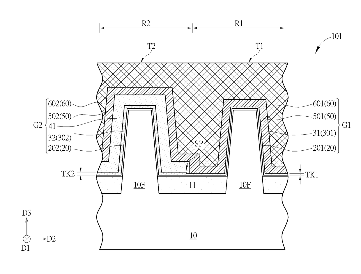
The present invention provides a method for manufacturing a semiconductor device with improved etching processes. By performing a first etching process before forming a first work function layer, the etching time for removing the first work function layer and thinning the barrier layer in a first region may be reduced. This may also improve the coverage of the first work function layer in a second region and enhance the electrical performance of the semiconductor device. The resulting device may have improved uniformity of electrical performance.

Problems solved by technology

The development of semiconductor integrated circuit technology progresses continuously and circuit designs in products of the new generation become smaller and more complicated than those of the former generation.
With the trend towards scaling down the size of semiconductor devices, however, conventional poly-silicon gates face problems such as inferior performance due to boron penetration and unavoidable depletion effects.
This increases equivalent thickness of the gate dielectric layer, reduces gate capacitance and worsens a driving force of the devices.

Method used


Image

  • Semiconductor device including barrier layer and manufacturing method thereof
  • Semiconductor device including barrier layer and manufacturing method thereof
  • Semiconductor device including barrier layer and manufacturing method thereof

Examples


first embodiment

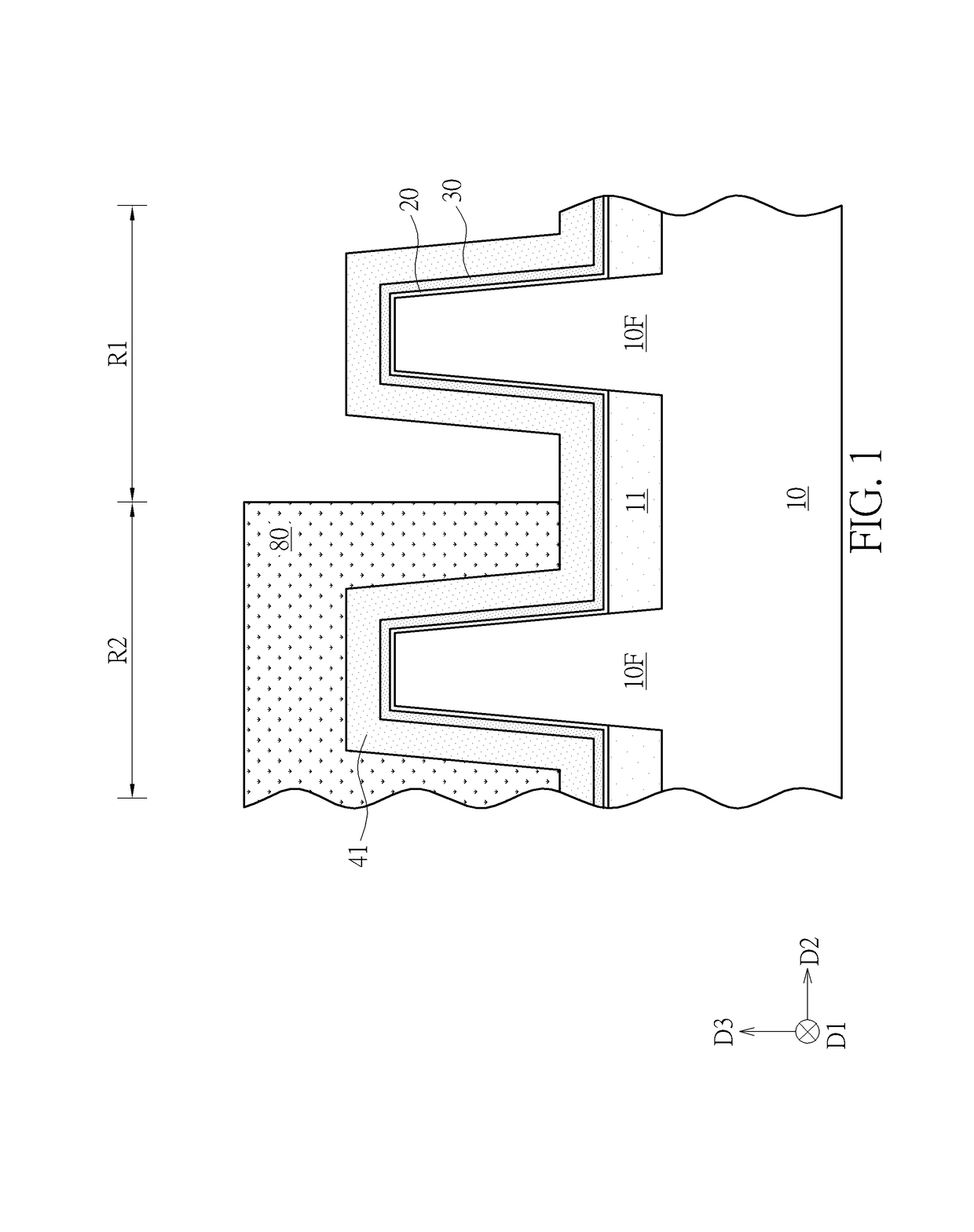
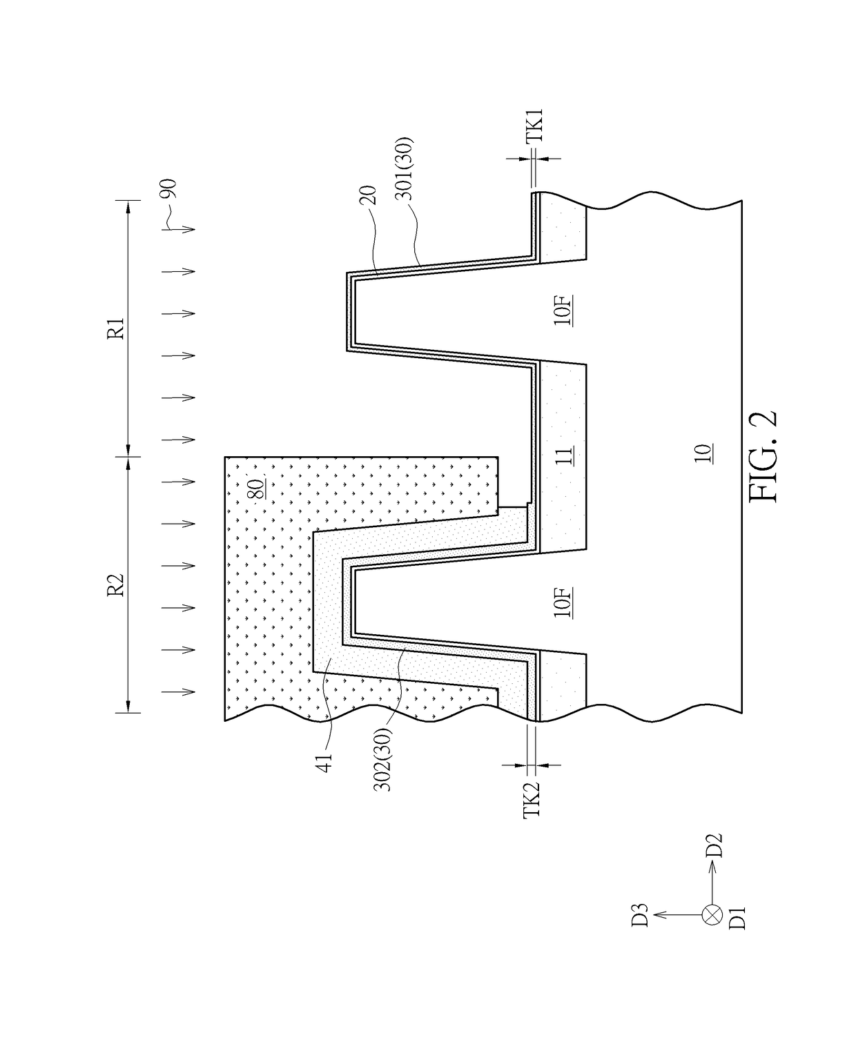
[0025]Please refer to FIG. 1 and FIG. 2. FIG. 1 and FIG. 2 are schematic drawings illustrating a manufacturing method of a semiconductor device according to the present invention. The manufacturing method of the semiconductor device in this embodiment includes the following steps. As shown in FIG. 1, a semiconductor substrate 10 is provided. The semiconductor substrate 10 in this embodiment may include a silicon substrate, an epitaxial silicon substrate, a silicon germanium substrate, a silicon carbide substrate, or a silicon-on-insulator (SOI) substrate, but not limited thereto. The semiconductor substrate 10 includes at least one fin structure 10F, and the fin structure 10F may include a fin structure made of a semiconductor material. In this embodiment, the semiconductor substrate 10 may include a plurality of the fin structures 10F. Each of the fin structures 10F may be elongated in a first direction D1, and the fin structures 10F may be repeatedly disposed in a second direction...

second embodiment

[0028]Please refer to FIGS. 3-7. FIGS. 3-7 are schematic drawings illustrating a manufacturing method of a semiconductor device according to the present invention. The manufacturing method of the semiconductor device in this embodiment includes the following steps. As shown in FIG. 3, the semiconductor substrate 10 is provided. The semiconductor substrate 10 includes the first region R1 and the second region R2 adjacent to the first region R1. The semiconductor substrate 10 may include a plurality of the fin structures 10F. The fin structures 10F are separated from one another by the shallow trench isolation 11. A part of the fin structures 10F may be disposed in the first region R1, and another part of the fin structures 10F may be disposed in the second region R2. The barrier layer 30 is then formed on the semiconductor substrate 10. Before the step of forming the barrier layer 30, the gate dielectric layer 20 may be conformally formed on the fin structures 10F and the shallow tre...


PUM


Abstract

A manufacturing method of a semiconductor device includes the following steps. A barrier layer is formed in a first region and a second region of a semiconductor substrate. The barrier layer formed in the first region is thinned before a step of forming a first work function layer on the barrier layer. The first work function layer formed on the first region is then removed. The process of thinning the barrier layer in the first region and the process of removing the first work function layer in the first region are performed separately for ensuring the coverage of the first work function layer in the second region. The electrical performance of the semiconductor device and the uniformity of the electrical performance of the semiconductor device may be improved accordingly.

Description

BACKGROUND OF THE INVENTION1. Field of the Invention[0001]The present invention relates to a semiconductor device and a manufacturing method thereof, and more particularly, to a semiconductor device including a barrier layer with different thicknesses in different regions and a manufacturing method thereof.2. Description of the Prior Art[0002]The development of semiconductor integrated circuit technology progresses continuously and circuit designs in products of the new generation become smaller and more complicated than those of the former generation. The amount and the density of the functional devices in each chip region are increased constantly according to the requirements of innovated products, and the size of each device has to become smaller accordingly.[0003]Poly-silicon is conventionally used as a gate electrode in semiconductor devices, such as the metal-oxide-semiconductor (MOS). With the trend towards scaling down the size of semiconductor devices, however, conventional...

Claims


Application Information

Patent Timeline
Patent Type & Authority Patents(United States)
IPC IPC(8): H01L27/092H01L29/51H01L21/8238H01L21/311
CPCH01L27/092H01L21/823828H01L29/517H01L21/31144H01L21/823857H01L21/82345H01L21/823821H01L21/823842H01L27/088H01L27/0924H01L29/4966H01L29/66545
Inventor LIN, CHUN-HAOHSIEH, SHOU-WEICHEN, HSIN-YU
Owner MARLIN SEMICON LTD
Learn More