
PZT transducer-horn integrated ultrasonic driving structure

a technology of ultrasonic driving and transducer horn, which is applied in the field of ultrasonic driving surgical devices for medical purposes, can solve the problems of not meeting the requirements of desired minimally-invasive abdominal surgery, and achieve the effect of reducing the contour dimension of the ultrasonic driving device and reducing the outer diameter

Inactive Publication Date: 2018-05-22
DALIAN UNIV OF TECH
View PDF5 Cites 2 Cited by
  • Summary
  • Abstract
  • Description
  • Claims
  • Application Information

AI Technical Summary

Benefits of technology

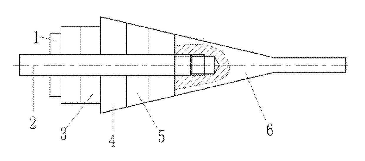
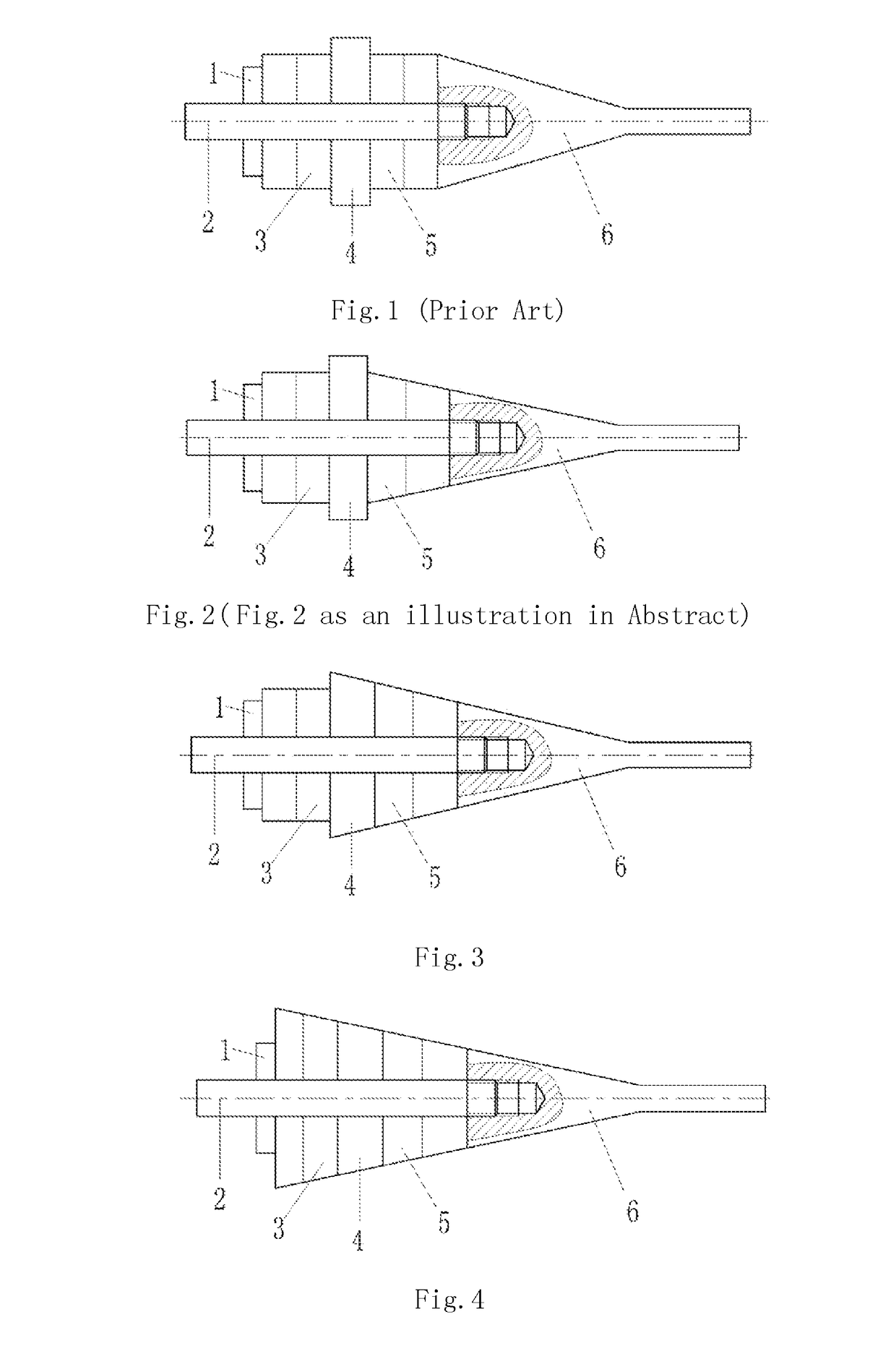
The patent describes a way to make a small ultrasonic device by combining a PZT transducer and a horn. This design reduces the thickness of the device and makes it easier to fit into smaller spaces. Overall, the device is made up of a nut, bolt, PZT circular stack, flange, PZT truncated stack, and horn. The right PZT truncated stack is a cone-shaped stack made up of PZT circular plates. By arranging and connecting these layers in a specific way, the device can vibrate effectively. The design reduces the size of the device, making it easier to handle and use. Overall, this technology makes it possible to make smaller ultrasonic devices with improved performance.

Problems solved by technology

Considering the separated design of PZT transducer and horn of the conventional driving structure, under the existing PZT material and ultrasonic generation and driving structure conditions, the contour dimension of the driving device is limited within a certain special scale, and the outer diameter ranges from 12 mm to 15 mm, resulting in the problem of not meeting the requirements for desired minimally-invasive abdominal surgery.

Method used


Image

  • PZT transducer-horn integrated ultrasonic driving structure
  • PZT transducer-horn integrated ultrasonic driving structure

Examples


Embodiment Construction

[0014]According to the invention, the piezoelectric transducer and the horn in an ultrasonic driving medical device are integrally designed such that without changing the overall dimension of PZT, the flange and PZT stacks are respectively designed and assembled to be a part of the horn, the PZT stacks having both electrical and mechanical conversion function and amplitude amplification function, and the dimension of the horn is relatively reduced, thereby achieving the purpose of reducing the outer diameter of the ultrasonic driving device.

[0015]An embodiment is as follows: a PZT transducer-horn integrated ultrasonic vibration structure, consists of a nut (1), a bolt (2), a left PZT circular stack (3), a circular flange (4), a right PZT truncated stack (5) and a horn (6); the horn (6), the right PZT truncated stack (5), the flange (4) and the left PZT circular stack (3) are arranged in sequence and serially connected via the bolt (2) and then fastened via the nut (1). As shown in F...


PUM


Abstract

A PZT transducer-horn integrated ultrasonic driving structure consists of a nut, a bolt, a left PZT circular stack, a flange, a right PZT truncated stack and a horn. The horn, the right PZT truncated stack, the flange and the left PZT circular stack are arranged in sequence and connected via the bolt and then fastened via the nut; the right PZT transducer is a truncated cone-shaped stack formed by PZT circular plates; and the right PZT transducer and the horn are integrated to form the ultrasonic driving structure. Considering the dimension of PZT on two sides of the flange and the horn meet the requirements for ultrasonic vibration node and antinode, the dimension of round contour of the circular PZT stack and flange is reduced to increase the thickness of the truncated PZT stack and flange. With the integrated structure, the effect of reducing the contour dimension of the ultrasonic driving surgical device can be obtained, and the outer diameter is reduced to the range of 8-10 mm as compared with the range of 12-15 mm in the prior art, thereby further meeting the application requirements.

Description

TECHNICAL FIELD[0001]The invention belongs to the field of medical ultrasonic driving surgical devices and application thereof, and relates to an ultrasonic vibration device of PZT (piezoelectric ceramic) transducer-horn integrated structure design and assembly.BACKGROUND ART[0002]Conventionally, a PZT transducer-horn ultrasonic driving structure, as shown in FIG. 1, consists of a nut (1), a bolt (2), a left PZT circular stack (3), a flange (4), a right PZT circular stack (5), and a horn (6). Under the existing PZT material and ultrasonic generation and driving structure conditions, the contour dimension of the driving device is limited within a certain special scale and the outer diameter is relatively large, which can not meet the requirements for minimally-invasive abdominal surgery. For the PZT transducer-horn integrated design and assembly, the dimension of PZT materials on two sides of the flange (4) and the shape of the horn should meet the requirements for ultrasonic vibrati...

Claims


Application Information

Patent Timeline
Patent Type & Authority Patents(United States)
IPC IPC(8): H01L41/04A61B17/86A61B17/00A61B17/32H10N30/50H10N30/80
CPCA61B17/8665A61B17/00234A61B2017/320088A61B2017/00402A61B17/320068A61B2017/22027B06B1/0611H10N30/505
Inventor WANG, RUIWANG, XUYUEWANG, XIAOMING
Owner DALIAN UNIV OF TECH
Learn More