Method for operating a steam turbine plant

a steam turbine and plant technology, applied in steam engine plants, machines/engines, mechanical equipment, etc., can solve the problems of inability to account for prior art, affecting the power output affecting the efficiency of steam turbine plants, so as to reduce the tendency for condensation inside the turbines, cost-effective, and stabilize the grid

Active Publication Date: 2018-05-29
SIEMENS ENERGY GLOBAL GMBH & CO KG
View PDF28 Cites 0 Cited by
  • Summary
  • Abstract
  • Description
  • Claims
  • Application Information

AI Technical Summary

Benefits of technology

[0013]In parallel or also alternatively, the steam generator can advantageously also be kept warm. This is achieved by the continuous feeding of a small amount of steam to the steam generator. The amount of steam is chosen such that the heat energy of the steam compensates for the heat losses from the steam generator. The steam generator thus remains at a relatively high temperature and can quickly be returned to operation at full load, for example when the gas turbine is started up in a gas-and-steam power station. This operating concept offers the option of keeping the steam turbine, and possibly the steam generator, warm so that the time required to start up the power station is shorter and the plant can be used for control purposes (for example, to balance power fluctuations in the grid).
[0015]According to the invention, the heat store is loaded whilst a power demand on the steam turbine plant from a power grid is below a preset threshold value. The loading thus takes place at a period of low power demand in the grid. As a result of the loading process, the output of the steam turbine, and hence of the power station, namely falls slightly for a short period of time. Once the store is loaded, the power station continues to be operated in grid-driven power mode.
[0017]In a further advantageous embodiment of the method, the heat store is loaded with superheated steam from the steam generator or the steam turbine. The steam has a higher energy level and thus permits quicker loading of the heat store. For this purpose, superheated steam is removed, for example, downstream from the high-pressure steam turbine and after reheating and fed to the heat store.
[0024]The advantages obtained with the invention consist in particular in the ability of the steam turbine part of a power station to be kept warm for a longer period of time, so that control power can be provided even without any fuel being consumed.
[0025]Adding only small quantities of additional steam as saturated steam from the store is hereby required. As a result, a slight drop in temperature occurs at the inlet of the steam turbine. However, the steam turbine is furthermore operated with superheated steam and the tendency for condensation inside the turbines is less.
[0026]The invention described can be implemented using available, cost-effective, passive components (drum store, hot-water and steam pipes). The operating range of the power station, for example a reduction in output from the removal of heat (hot water / steam) from the steam generator or an increase in output from the supply of additional steam to the steam turbine (from the store), is thus expanded in a technically simple fashion.

Problems solved by technology

However, because the maximum efficiency of the steam turbine is achieved only at full power, the power stations are, as a result of the throttling required to provide the power reserve, operated during standard operation with a slightly inferior efficiency in comparison with their maximum possible efficiency.
However, the prior art is not able to account for the fact that the power output of a steam turbine plant is affected during the loading of the steam store as a result of this loading process.

Method used


Image

  • Method for operating a steam turbine plant
  • Method for operating a steam turbine plant
  • Method for operating a steam turbine plant

Examples


Embodiment Construction

[0037]Identical parts are provided with the same reference numerals in all the drawings.

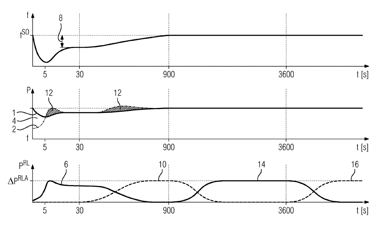
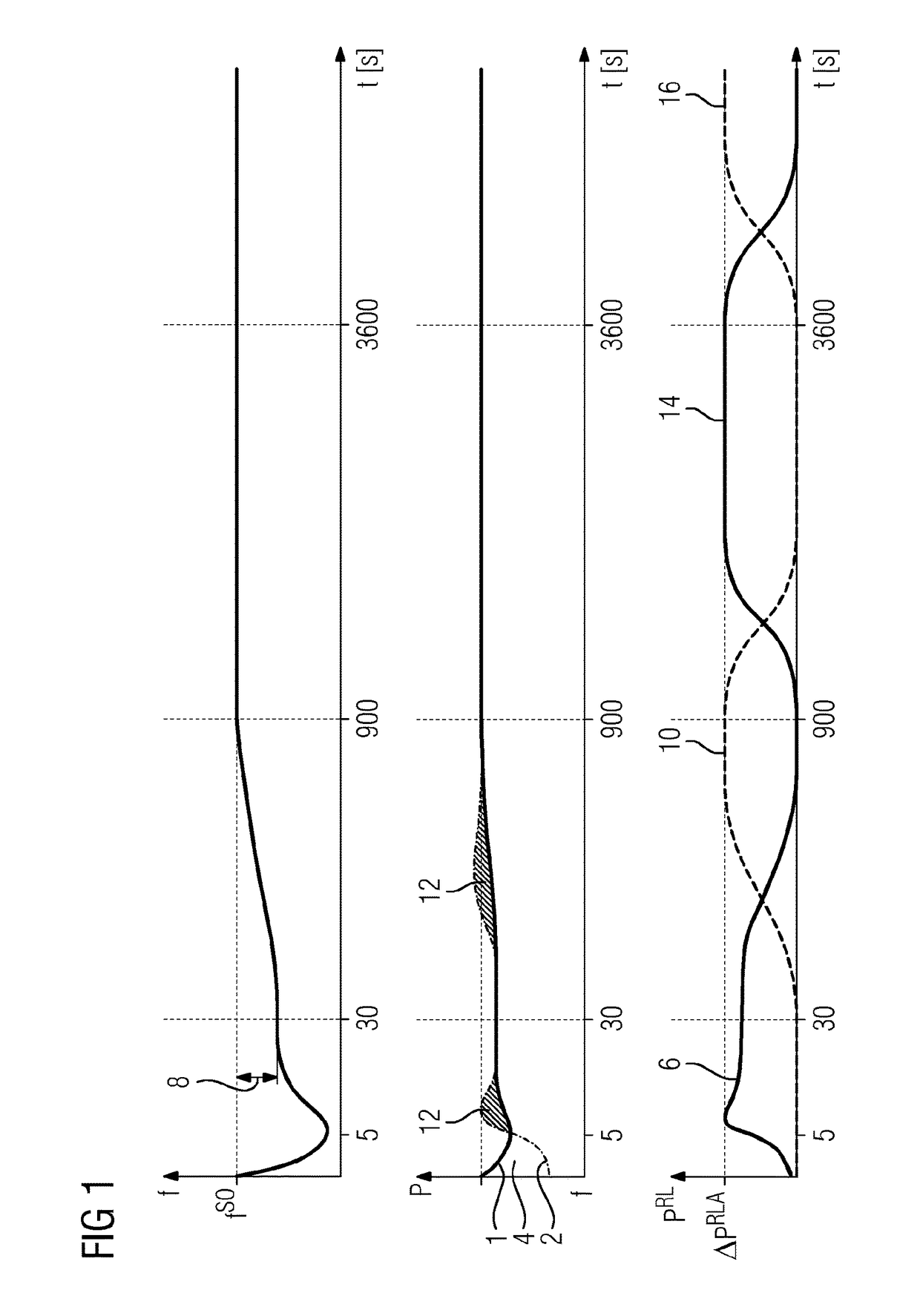
[0038]FIG. 1 shows a graph with a total of three separate systems of coordinates, arranged one above the other. These show, from top to bottom, the grid frequency f in an electricity grid, plotted against time, level of consumption and generator power P in the electricity grid, plotted against time, and the different types of control power PRL in the electricity grid, plotted against time. The time scales are identical and are given in seconds, whilst the frequency f, power P and control power PRL scales are not given because the absolute scales are not relevant for the following description.

[0039]Attempts are made in an electricity grid, using a power station management approach, to balance power obtained in power stations with power removed by consumers and losses during transportation. If the expected power requirement does not correspond to the power supply, the discrepancy must be compensate...


PUM


Abstract

A method for operating a steam turbine plant including a steam turbine and a steam generator allows a power reserve to be provided whilst simultaneously maintaining a high level of efficiency in the normal mode of operation. The steam turbine plant includes a heat reservoir which is associated with the steam turbine, from which the steam is removed and is fed to the steam turbine. The steam is fed to the steam turbine when the steam generator is not in operation.

Description

CROSS REFERENCE TO RELATED APPLICATIONS[0001]This application is the US National Stage of International Application No. PCT / EP2014 / 069257 filed Sep. 10, 2014, and claims the benefit thereof. The International Application claims the benefit of German Application No. DE 102013219189.8 filed Sep. 24, 2013. All of the applications are incorporated by reference herein in their entirety.FIELD OF INVENTION[0002]The invention relates to a method for operating a steam turbine plant with a steam turbine and a steam generator.BACKGROUND OF INVENTION[0003]Steam turbine plants of the type mentioned at the beginning are known from the prior art and are used to generate electricity in an electricity grid. Control power is held in readiness in order to maintain the grid frequency in the event of unforeseen disruptions. Every grid operator needs to make available 2% of its temporary generation capacity as a primary control power reserve. This primary control power reserve is typically provided by la...

Claims


Application Information

Patent Timeline
Patent Type & Authority Patents(United States)
IPC IPC(8): F01K13/02F01K7/22F01K3/00F01K7/16F01K23/10F01K3/02F01K23/18
CPCF01K13/02F01K3/004F01K3/008F01K3/02F01K7/22F01K23/101F01K23/18F01K7/16Y02E20/16
Inventor LENK, UWETREMEL, ALEXANDER
Owner SIEMENS ENERGY GLOBAL GMBH & CO KG
Why Eureka
Try Eureka