
Air stable infrared photodetectors from solution-processed inorganic semiconductors

a technology of inorganic semiconductors and stable infrared light, which is applied in the direction of optical radiation measurement, instruments, spectrometry/spectrophotometry/monochromators, etc., can solve the problems of limited market penetration of photodetectors and the inability of conventional single-crystalline semiconductors to integrate with flexible electronics, etc., to achieve low noise and stability

Active Publication Date: 2018-05-29
UNIV OF FLORIDA RES FOUNDATION INC
View PDF11 Cites 0 Cited by
  • Summary
  • Abstract
  • Description
  • Claims
  • Application Information

AI Technical Summary

Benefits of technology

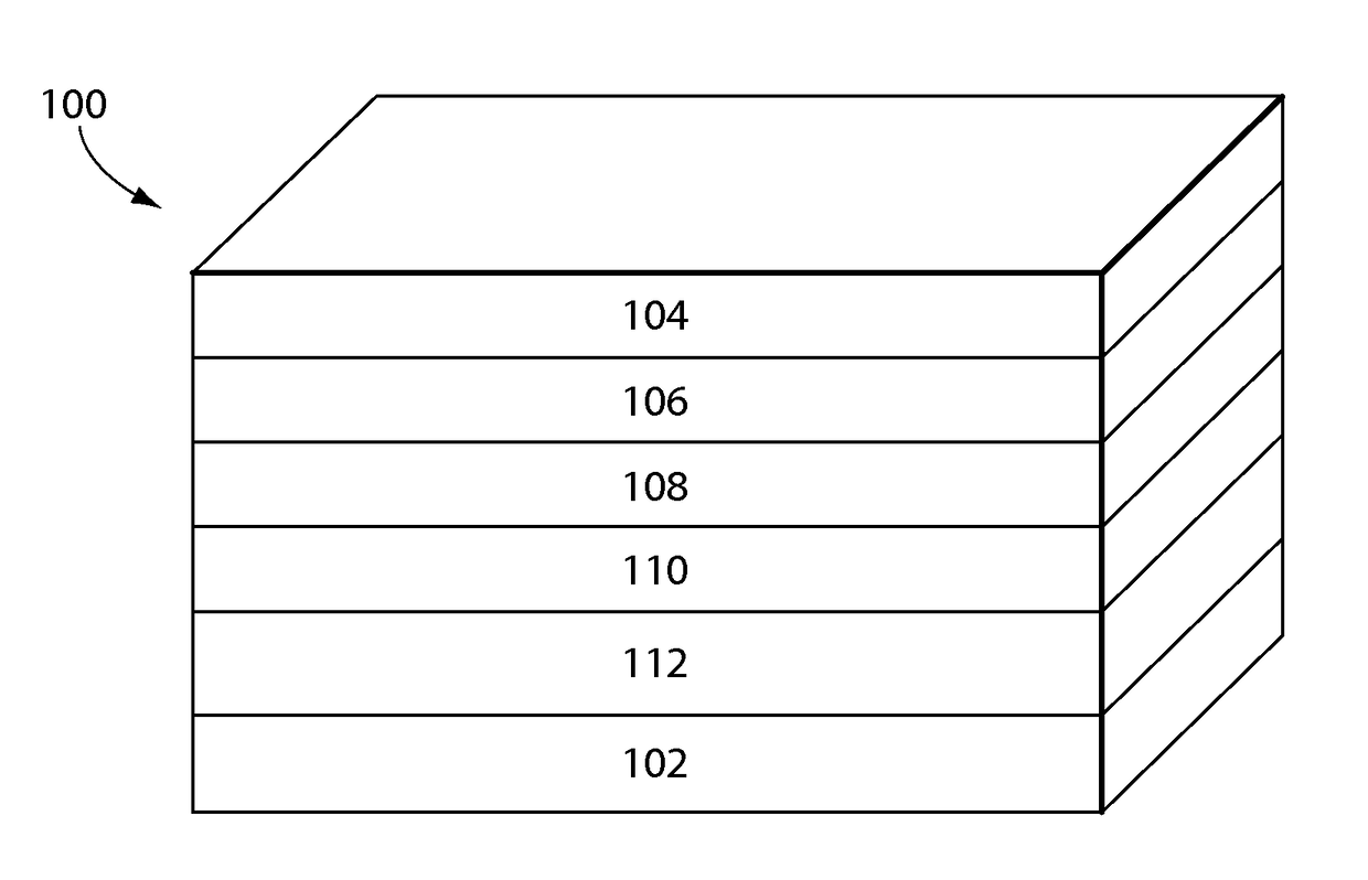
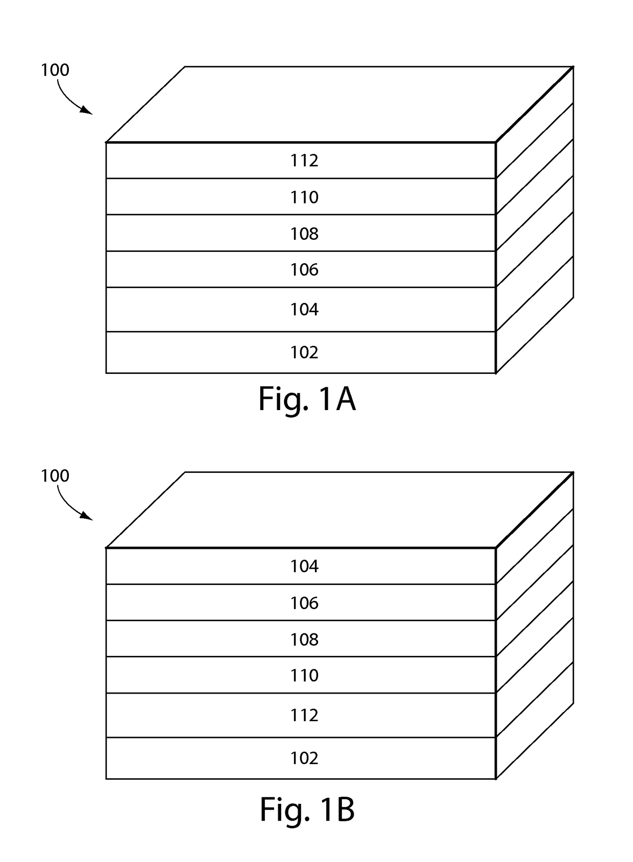
This patent describes photodetectors that use semiconducting inorganic nanoparticles to detect infrared and high-energy electromagnetic radiation. The nanoparticles are positioned between a hole transport layer and an electron transport layer, with metal oxide coatings providing low noise and stability in air without encapsulation. The nanoparticles can be lead chalcogenides, mercury chalcogenides, III-V semiconductors, silicon, or any combinations thereof. The detector can be a broadband photodetector that is responsive to at least the visible and infrared regions of the electromagnetic spectrum. The technical effects of this patent are improved efficiency and sensitivity of photodetectors to a wider range of electromagnetic radiation wavelengths.

Problems solved by technology

Conventional photodetectors are typically made under vacuum processing conditions that are incompatible with high throughput, inexpensive fabrication techniques.
The market penetration of the photodetectors is limited due to the high fabrication cost and / or low performance of the photodetectors.
Conventional single-crystalline semiconductors are precluded from integration with flexible electronics, particularly those including organic materials, due to the incompatibility of the processing conditions required for the semiconductors.

Method used


Image

  • Air stable infrared photodetectors from solution-processed inorganic semiconductors
  • Air stable infrared photodetectors from solution-processed inorganic semiconductors
  • Air stable infrared photodetectors from solution-processed inorganic semiconductors

Examples


example

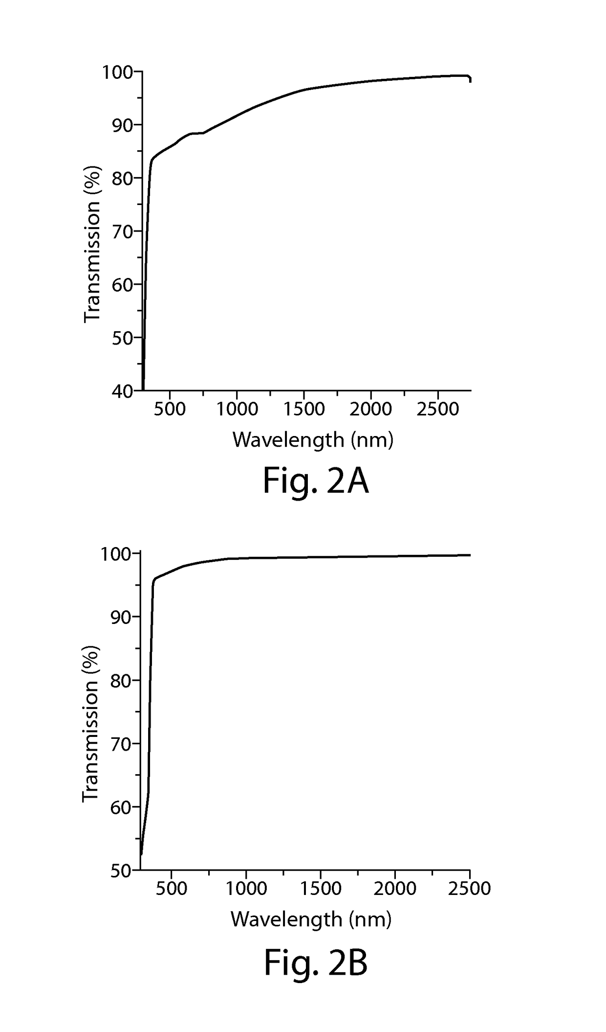
[0049]This Example describes fabrication of layers in a broadband multispectral photodetector comprising a PbS quantum dot photoactive layer, a NiO hole transport electron blocking layer, and a ZnO electron transport hole blocking layer. The Example also illustrates the resulting advantageous properties of the photodetector.

NiO Layer Preparation

[0050]A NiO precursor solution is prepared where a 0.1 M solution of nickel acetate in ethanol is combined with ethanolamine in a 1:1 mole ratio. The NiO precursor solution is spin coated on the anode and heated in air for one hour. The temperature of heating can be 275° C. to 500° C. or more to give a continuous film of the NiO.

PbS Quantum Dot Layer

[0051]A 1 M solution of hexamethyldisilathiane ((TMS)2S) in octadecane is injected into a vigorously stirred 0.004 M solution of lead oxide in octadecane and oleic acid at a temperature of 110° C. and 150° C. After 3-5 minutes the reaction is quenched by the addition of chilled isopropanol. After ...


PUM

PropertyMeasurementUnit
external quantum efficiencyaaaaaaaaaa
timeaaaaaaaaaa
bias voltageaaaaaaaaaa

Abstract

A photodetector has a photoactive layer of semiconducting inorganic nanoparticles positioned between a hole transport electron blocking layer of a first metal oxide and an electron transport hole blocking layer of a second metal oxide. The nanoparticles are responsive to electromagnetic radiation in at least the infrared region of the spectrum. The first metal oxide can be NiO, and the second metal oxide can be ZnO or TiO2. The metal oxide layers render the photodetector stable in air, even in the absence of an encapsulating coating around the photodetector. The photodetector has a P-I-N structure.

Description

RELATED APPLICATIONS[0001]The present application is a U.S. national stage filing under 35 U.S.C. § 371 based on International Application No. PCT / US2014 / 053546, filed Aug. 29, 2014, which claims priority under 35 U.S.C. § 119(e) to U.S. Provisional Application Ser. No. 61 / 871,579, filed Aug. 29, 2013, each of which is hereby incorporated by reference herein in its entirety, including any figures, tables, or drawings.BACKGROUND OF INVENTION[0002]Optical communications, remote sensing, spectroscopy, optoelectronics and imaging are just a few of the applications enabled by infrared and broadband photodetectors. In these photodetectors, a photosensitive material absorbs optical signals in the visible range and / or short wavelength infrared (SWIR) range and transforms the optical signals into electronic signals. Conventional photodetectors are typically made under vacuum processing conditions that are incompatible with high throughput, inexpensive fabrication techniques. The market penet...

Claims


Application Information

Patent Timeline
Patent Type & Authority Patents(United States)
IPC IPC(8): H01L31/107H01L31/032H01L31/101H01L31/0296H01L31/0352H01L31/0216H01L31/105H01L31/18H01L31/109B82Y40/00B82Y20/00
CPCH01L31/035218H01L31/0296H01L31/02165H01L31/0324H01L31/101H01L31/105H01L31/18H01L31/109Y10S977/954B82Y20/00B82Y40/00Y10S977/774Y10S977/813Y10S977/893G01J1/44G01J3/108G01J2001/444H01L31/0352H01L31/08
Inventor SO, FRANKYMANDERS, JESSE ROBERTCHEN, SONGKLUMP, ERIK D.LAI, TZHUNG-HANTSANG, SAI-WING
Owner UNIV OF FLORIDA RES FOUNDATION INC
Learn More