Optical fiber cable

a fiber optic cable and optical fiber technology, applied in the field of optical fiber cables, can solve the problems of prohibitively expensive, physical winding of the fiber around the object to be monitored, and may not be possible, and achieve the effects of low bending loss, good performance, and high longitudinal sensing resolution of the resulting cabl

Active Publication Date: 2018-06-05
SILIXA +1
View PDF38 Cites 14 Cited by
  • Summary
  • Abstract
  • Description
  • Claims
  • Application Information

AI Technical Summary

Benefits of technology

[0010]The provision of a cable formed from wound fiber according to embodiments of the present invention provides significant advantages in terms of ease of use and installation as well as improved sensitivity. In particular, the cable can simply be treated as a coherent whole which can be installed very easily by simply immersing it inside a volume or laying it next to an object to be monitored (rather than having to wrap fiber around the whole object, as in the prior art). In addition, in area sensing applications, using a cable according to the present invention in place of a run of fiber provides for significantly increased sensing spatial resolution, in that more acoustic samples can be obtained per length of such a cable than for a corresponding length of fiber installed in the same position.
[0011]In some embodiments the helical pitch can be different at different points along the cable. This allows for different spatial resolution to be obtained at different points on the cable, dependent on the helical pitch. In addition, it may be that in some embodiments the fiber is not helically wound round the cable core at all points along the cable, but instead runs along the cable core parallel thereto between regions of helical windings. In so doing fiber bending losses are minimised in those regions where the fiber is not helically wound, and the total length of the cable can be increased. The regions of helical winding can thus be provided in those regions of the cable that when installed will be next to infrastructure to be monitored that requires higher spatial resolution, with other parts of the infrastructure that require lower spatial resolution monitoring being provided with regions of the cable with helical windings of larger pitch, or with straight sections of fiber, as appropriate. In this way, a bespoke sensing cable can be provided with its sensing spatial resolution adapted along its length for the specific installation in which it will be placed.
[0013]Embodiments of the present invention also provide for specially designed clamps to secure the optical fiber cables to infrastructure to be monitored, and in particular pipework-type infrastructure such as oil well casing or tubing, by way of example. The clamps are designed to transfer acoustic strain vibrations from the pipework to be monitored to the optical fiber cable in a manner that allows the vibrations to be effectively transmitted to the cable. In one embodiment a Figure of 8 clamp arrangement is believed to be particularly effective at transmitting the acoustic strain vibrational energy from the infrastructure being monitored to the cable. For example, in this case, the tensional hoop strain from a pipework is translated to a compressional hoop strain around the optical fiber cable. In another embodiment a clamp arrangement is provided where magnets exert a lateral force on the cable so as to make the cable more sensitive to vibrations from a direction of incidence substantially orthogonal to the lateral force, the cable being placed against an article to be monitored so that the article contacts the cable in the orthogonal direction.
[0017]As noted above, in embodiments of the invention the fiber optic cable is used with a distributed acoustic sensing system. In particular, we have found such a cable to be particularly effective at allowing a DAS system provided with such a cable to conduct flow monitoring of pipework. In particular, the higher spatial resolution obtained from the helical cable of the present invention allows for improved eddies detection and tracking in pipework, which in turn, by tracking the strain induced vibration by the eddies along the pipework, gives information as to the fluid flow in the pipe as the eddies move with the fluid flow.
[0018]Finally, a further advantage is obtained in that the increase in sensing spatial resolution is obtained without requiring any substantial changes to the DAS or DTS equipment itself. Such a cable is therefore backwards compatible with existing DAS or DTS equipment, as well being used with new equipment. Account of the cable configuration needs to be taken when processing DAS or DTS outputs, however, but such processing can be done in software; no new sensor hardware is required.

Problems solved by technology

Moreover, physically winding the fiber around the object to be monitored may not be possible, or be prohibitively expensive.

Method used


Image

  • Optical fiber cable
  • Optical fiber cable
  • Optical fiber cable

Examples


example 1

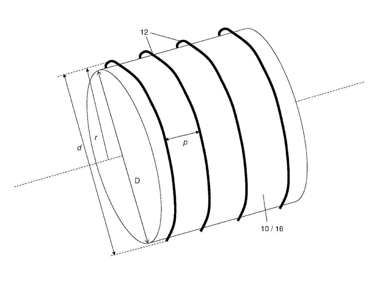
[0068]Cable core, d=10 mm, r=5 mm[0069]Fibre, d=3 mm, r=1.5 mm, 1000 turns[0070]Total Radius=6.5 mm[0071]Pitch=3 mm[0072]θ=0.07332 radians[0073]L=40,950.7 mm=40.95 m[0074]=>˜8 sensing points, sensing point every ˜122 turns[0075]Longitudinal Sensing Resolution ˜36.63 cm

example 2

[0076]Cable core, d=50 mm, r=25 mm[0077]Fibre, d=3 mm, r=1.5 mm, 1000 turns[0078]Total Radius=26.5 mm[0079]Pitch=3 mm[0080]θ=0.01802 radians[0081]L=166,531.4 mm=166.5 m[0082]=>˜33 sensing points, sensing point every ˜30 turns[0083]Longitudinal Sensing Resolution ˜9.00 cm

example 3

[0084]Cable core, d=150 mm, r=75 mm[0085]Fibre, d=3 mm, r=1.5 mm, 1000 turns[0086]Total Radius=76.5 mm[0087]Pitch=3 mm[0088]θ=0.00624 radians[0089]L=480,673.04 mm=480.7 m[0090]=>˜96 sensing points, sensing point every ˜10 turns[0091]Longitudinal Sensing Resolution ˜3.12 cm


PUM


Abstract

Embodiments of the present invention provide a cable for optical fiber sensing applications formed from fiber wound around a cable core. A protective layer is then preferably placed over the top of the wound fiber, to protect the fiber, and to help keep it in place on the cable core. The cable core is preferably of a diameter to allow bend-insensitive fiber to be wound thereon with low bending losses. The effect of winding the fiber onto the cable core means that the longitudinal sensing resolution of the resulting cable is higher than simple straight fiber, when the cable is used with an optical fiber sensing system such as a DAS or DTS system. The achieved resolution for the resulting cable is a function of the fiber winding diameter and pitch, with a larger diameter and reduced winding pitch giving a higher longitudinal sensing resolution.

Description

CROSS-REFERENCE TO RELATED APPLICATIONS[0001]This application claims priority under 35 U.S.C. § 371 to Patent Cooperation Treaty Application No. PCT / GB2014 / 053100, filed Oct. 15, 2014, which claims priority to GB Application No. 1318254.8, filed Oct. 15, 2013, the entire contents of which are incorporated herein by reference.TECHNICAL FIELD[0002]The present invention relates to a cable formed from wound optical fiber. The cable is particularly useful for optical fiber sensing purposes, for example with a distributed acoustic sensor (DAS) system, or distributed temperature sensor (DTS) systems. In particular the spatial sensing resolution of such a system will typically be increased by using such a cable. Furthermore the cable can be used for enhanced measurements such as distributed flow and seismic profiling.BACKGROUND TO THE INVENTION AND PRIOR ART[0003]Distributed acoustic sensor (DAS) systems and distributed temperature sensor (DTS) systems are known in the art. Both DAS and DTS...

Claims


Application Information

Patent Timeline
Patent Type & Authority Patents(United States)
IPC IPC(8): G02B6/44G01D5/353G01F1/66
CPCG01F1/661G02B6/4415G01D5/3537G01D5/35374G01H9/004G01K11/32G01D5/35377G02B6/4479G02B6/449F16G11/00E21B47/01F16G11/04G01D5/353
Inventor FARHADIROUSHAN, MAHMOUDFINFER, DANIELMAHUE, VERONIQUEPARKER, TOMSHATALIN, SERGEYSTRUSEVICH, DMITRY
Owner SILIXA
Why Eureka
Try Eureka