Supercharge Your Innovation With Domain-Expert AI Agents!

Battery module having bus bar assembly and battery pack comprising the same

a battery module and bus bar technology, which is applied in the direction of secondary cells, battery components, battery maintenance/maintenance, etc., can solve the problems of low manufacturing cost of pouch-shaped batteries, tool-induced short circuits, and difficulty in assembly of such members, so as to prevent misassembly of the battery module or a short circuit in the battery module during manufacture. , to achieve the effect of excellent structural stability

Active Publication Date: 2018-06-12
LG ENERGY SOLUTION LTD
View PDF39 Cites 4 Cited by
  • Summary
  • Abstract
  • Description
  • Claims
  • Application Information

AI Technical Summary

Benefits of technology

The present invention is a battery module that is small and stable, with individual battery cells connected in parallel using a special bus bar assembly. This design makes it easy to assemble the battery module and prevents misassembly or short circuits during manufacture.

Problems solved by technology

In particular, much interest is currently focused on the pouch-shaped battery, which uses an aluminum laminate sheet as a sheathing member, because the pouch-shaped battery is lightweight and the manufacturing cost of the pouch-shaped battery is low.
Particularly, in a case in which a plurality of battery cells is used to constitute the battery module or a plurality of cell modules, each of which includes a predetermined number of battery cells, is used to constitute the battery module, a plurality of members, such as bus bars, for mechanical fastening and electrical connection between the battery cells or the cell modules is generally needed and, as a result, a process of assembling such members is very complicated.
In this case, however, a short circuit due to a tool may occur during electrical connection of the battery module.
On the other hand, the battery module may be misassembled.
Even in these methods, however, additional members are needed with the result that the number of unnecessary parts is increased.
There is needed a space for coupling, welding, or soldering the mechanical fastening and electrical connection members with the result that the total size of a battery system is increased.

Method used


Image

  • Battery module having bus bar assembly and battery pack comprising the same
  • Battery module having bus bar assembly and battery pack comprising the same
  • Battery module having bus bar assembly and battery pack comprising the same

Examples


Embodiment Construction

[0048]Now, preferred embodiments of the present invention will be described in detail with reference to the accompanying drawings. It should be noted, however, that the scope of the present invention is not limited by the illustrated embodiments.

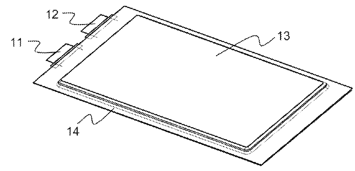
[0049]FIG. 1 is a perspective view showing a pouch-shaped battery cell according to the present invention.

[0050]Referring to FIG. 1, there is shown a plate-shaped battery cell 10 having electrode terminals (a cathode terminal 11 and an anode terminal 12) formed at one end thereof. Specifically, the plate-shaped battery cell 10 is configured to have a structure in which an electrode assembly (not shown) is mounted in a pouch-shaped case 13 formed of a laminate sheet including a metal layer (not shown) and a resin layer (not shown) and a sealed portion 14 is formed by thermal welding. The plate-shaped battery cell 10 may be commonly called a ‘pouch-shaped battery cell.’

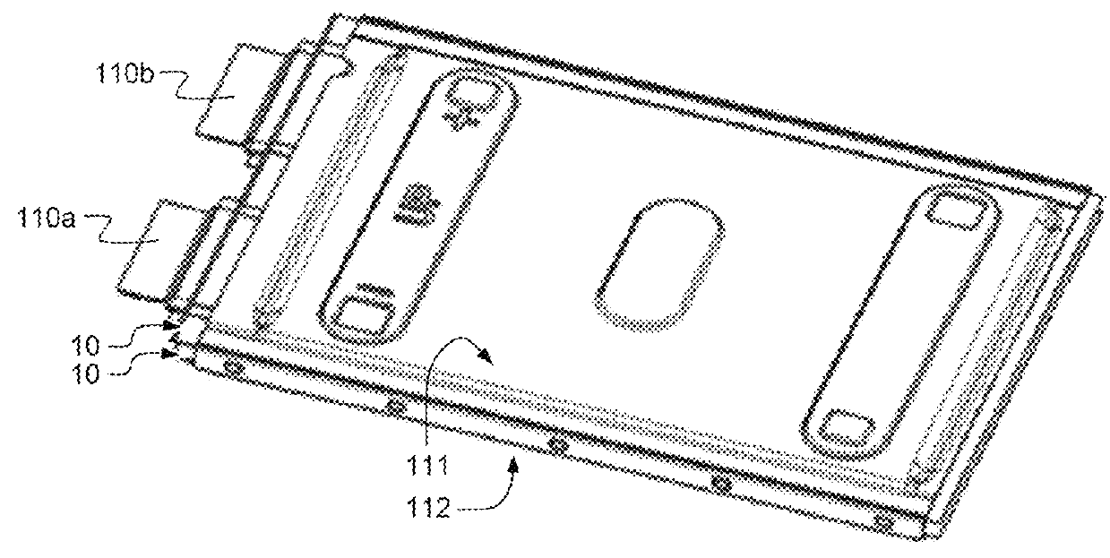
[0051]FIG. 2 is a perspective view showing a unit cell (cell assembly) conf...


PUM

PropertyMeasurementUnit
electrical insulationaaaaaaaaaa
sizeaaaaaaaaaa
weightaaaaaaaaaa

Abstract

Disclosed herein is a battery module including a unit module assembly including unit modules, each of which includes a plurality of battery cells or a plurality of cell assemblies, each of which includes two or more battery cells, as unit cells, the unit modules being arranged while being adjacent to each other, each of the unit modules having electrode terminals arranged at one side thereof, a battery disconnect unit (BDU) arranged at one side of the unit module assembly, the battery disconnect unit having terminal connection parts arranged at the same side as the electrode terminals, a module case in which the unit modules of the unit module assembly are mounted, the electrode terminals of the unit modules being exposed through the module case, and a bus bar assembly including a cover plate mounted on the electrode terminals of the unit modules at the module case, the cover plate being formed of an insulative material, and two more bus bars mounted to the cover plate.

Description

TECHNICAL FIELD[0001]The present invention relates to a battery module having a bus bar assembly and a battery pack including the same and, more particularly, to a battery module including a unit module assembly including unit modules, each of which includes a plurality of battery cells or a plurality of cell assemblies, each of which includes two or more battery cells, as unit cells, the unit modules being arranged while being adjacent to each other, each of the unit modules having electrode terminals arranged at one side thereof, a battery disconnect unit arranged at one side of the unit module assembly, the battery disconnect unit having terminal connection parts arranged at the same side as the electrode terminals, a module case in which the unit modules of the unit module assembly are mounted, the electrode terminals of the unit modules being exposed through the module case, and a bus bar assembly including a cover plate mounted on the electrode terminals of the unit modules at...

Claims


Application Information

Patent Timeline
Patent Type & Authority Patents(United States)
IPC IPC(8): H01M2/20H01M2/34H01M2/30H01M50/178H01M50/211H01M50/249H01M50/507H01M50/509H01M50/517H01M50/55H01M50/593
CPCH01M2/206H01M2/34H01M2/30H01M2220/20H01M10/4207H01M10/425H01M50/517H01M50/178H01M50/211H01M50/509H01M50/593H01M50/507H01M50/55H01M50/249B60L2270/145B60L58/21B60L50/66Y02T10/70Y02E60/10H01M50/20H01M50/531
Inventor KIM, JUHANSHIN, JIN-KYULEE, BUM HYUNKIM, TAEYEOP
Owner LG ENERGY SOLUTION LTD
Features
  • R&D
  • Intellectual Property
  • Life Sciences
  • Materials
  • Tech Scout
  • Unparalleled Data Quality
  • Higher Quality Content
  • 60% Fewer Hallucinations
Learn More