Air intake arrangement for internal combustion engine

a technology for air intake and internal combustion engines, which is applied in the direction of machines/engines, combustion-air/fuel-air treatment, electric control, etc., can solve the problems of difficult effective inducing swirling, difficult to reduce the acceleration response of fuel supply, and the obtained swirl is sometimes weaker and sometimes stronger than expected, so as to reduce the deposition ra

Inactive Publication Date: 2001-07-10
HITACHI LTD
View PDF33 Cites 12 Cited by
  • Summary
  • Abstract
  • Description
  • Claims
  • Application Information

AI Technical Summary

Benefits of technology

A second object of the present invention is to provide an air intake arrangement for an engine having means for inducing a swirl which shows a desirable air intake characteristic and suppress reduction of engine output during an engine full load operation.
A third object of the present invention is to provide an air intake arrangement having a high stability during an engine idling operation and a high response characteristic during a torque-up operation in response to actuation of an auxiliary device.
Still further, since the total volume of the auxiliary gas passage can be determined smaller than that of the main air passage, a necessary amount of air can be promptly supplied to the engine, thereby the response characteristic of the arrangement during idling operation, torque-up operation and EGR operation is improved.
Moreover, since the mounting member, fuel piping and air piping for fuel atomization for the fuel injection valve are formed integrally with the air intake conduit, the fuel injection valve can be placed close to the central axis of the air intake conduit, thereby an angle formed by .Iadd.the .Iaddend.fuel atomization axis and the central axis of the air intake conduit can be reduced. Further, the air intake conduit can be optimally designed in accordance with a spreading configuration of the fuel atomization so as to reduce a deposition rate on the inner wall of the air intake conduit of the atomized fuel injected from the fuel injection valve. With these measures the fuel deposition on the air intake conduit is reduced.

Problems solved by technology

In the conventional air intake arrangement which is designed to generate a swirl, there is provided an intake air control valve in a main air passage near an air inlet valve, therefore there arises a problem that the intake air control valve constitutes a resistance to the intake air during an engine full load operation and effects to reduce the engine output.
Further, when the air intake valve is closed, fuel deposits onto the air intake valve and causes a problem which reduces an acceleration response of fuel supply.
Further, since the direction of intake air is determined by the main air passage itself, it is difficult to effectively induce a swirling.
In both cases, an adjustable range of the swirling strength depending on operating conditions of the engine is limited, and there arised a problem that an obtained swirl is sometimes weaker and sometimes stronger than that .[.reqired.].
On the other hand, when the intake air control valve is opened, the air intake passage is narrowed by the existence of the swirl port and the air intake characteristic of the passage including the straight port and the swirl port is deteriorated, namely which caused a problem of reducing the maximum engine output.
Further, when air for an engine idling and for a torque-up operation is introduced into the collector which is a collecting portion of the air intake conduits, there arised a problem of deteriorating a response characteristic of intake air due to the large volume of the collector.
Likely, when EGR gas is introduced into the collector, the EGR gas interfers .Iadd.with .Iaddend.the combustion, in particular, when it is required to accelerate combustion by means of swirling it is difficult to uniformly introduce the EGR gas to the respective cylinders of the engine.
Further, during a transient engine operation a response of EGR gas supply delays and the combustion of the mixture gas is extremely interfered .Iadd.with .Iaddend.depending on the engine operating condition which .[.arised.].
.Iadd.created .Iaddend.a problem of impeding a large amount of EGR gas introduction.

Method used


Image

  • Air intake arrangement for internal combustion engine
  • Air intake arrangement for internal combustion engine
  • Air intake arrangement for internal combustion engine

Examples


Embodiment Construction

Hereinbelow, embodiments of the present invention are explained with reference to the drawings.

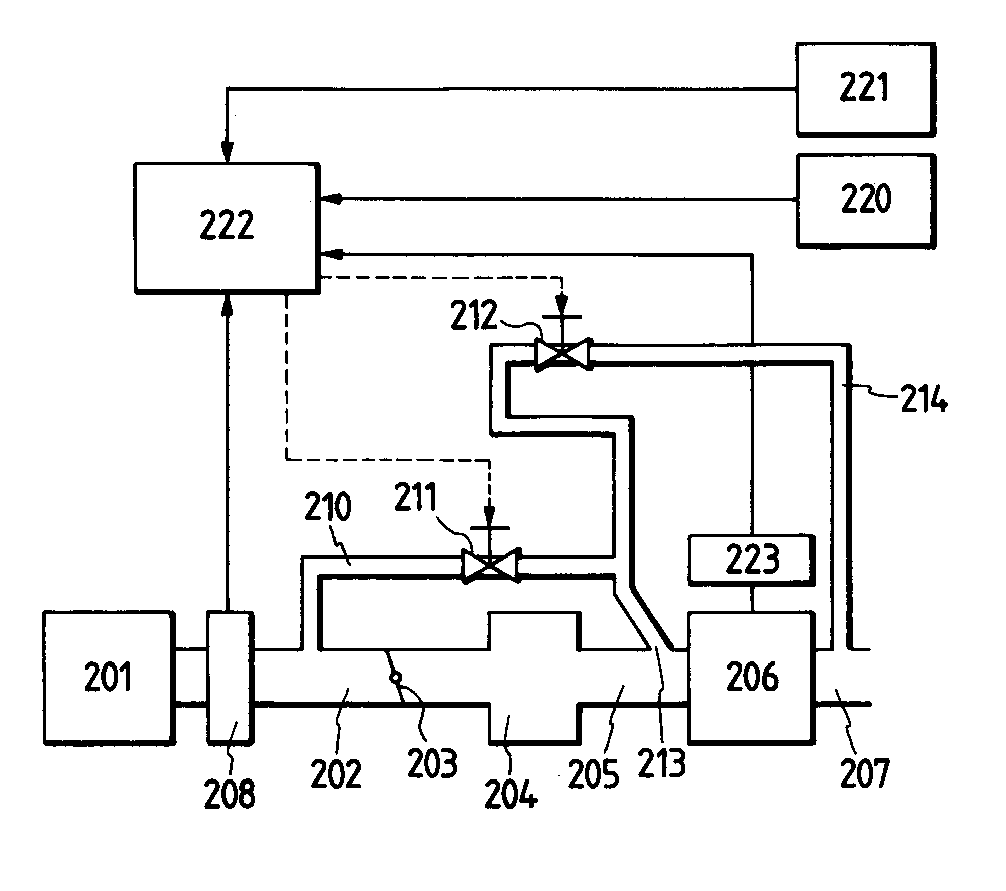
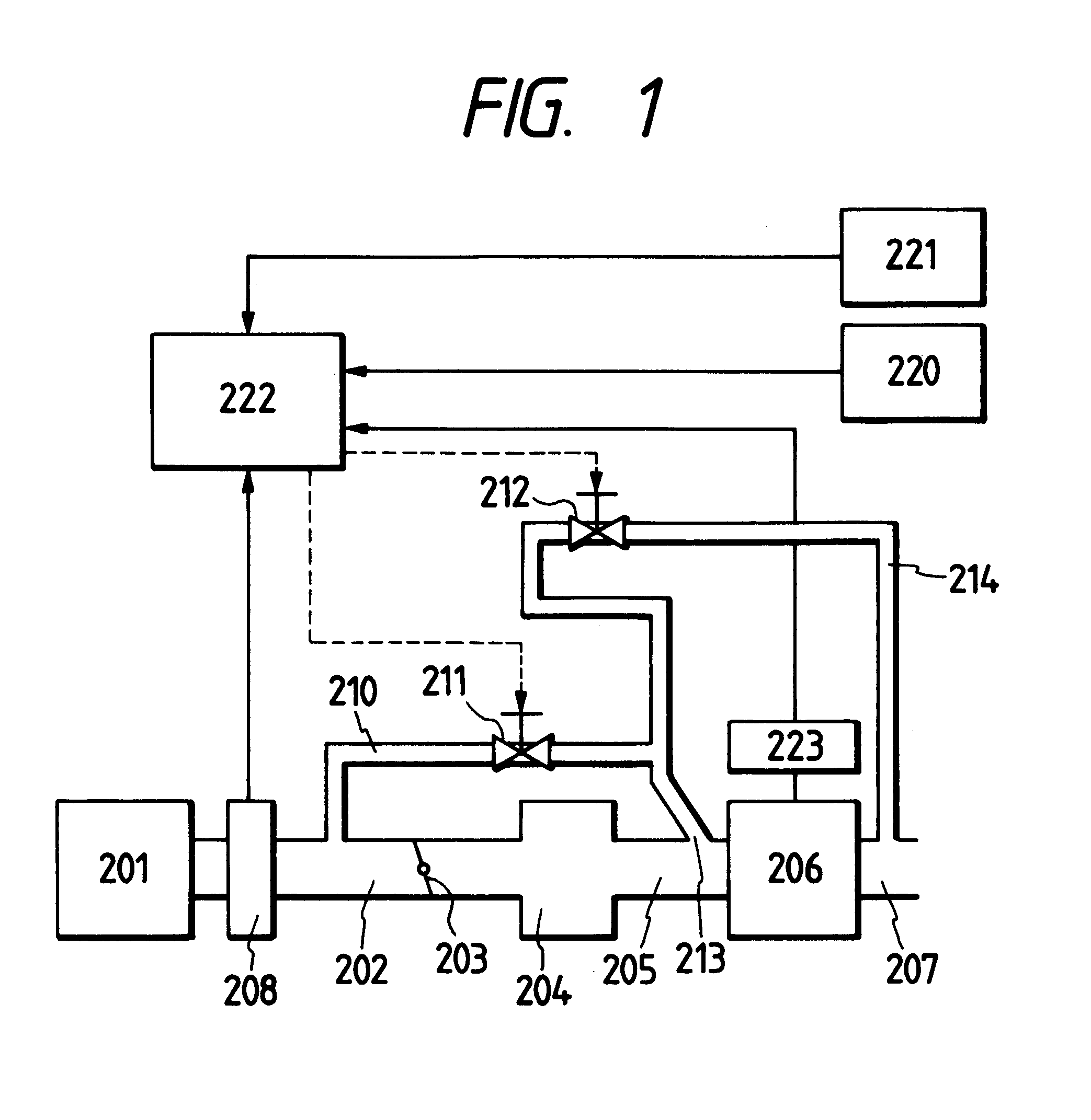
FIG. 1 shows one embodiment of the present invention. Inlet air is introduced from an air cleaner 201, and the flow rate thereof is measured by an air flow meter 208. An amount of air passing through a main passage 202 is adjusted by a throttle valve 203 and then distributed for respective engine cylinders from a collector 204 and thereafter introduced into an engine 206 via respective independent air intake conduits 205. In the present embodiment, an auxiliary gas passage 210 is provided in parallel with the respective independent air intake conduits 205. Air flow rate passing through the auxiliary gas passage 210 is adjusted through a control of an intake air control valve 211 by a computer 222 based on a signal from an acceleration pedal opening degree detecting means 221, an ON / OFF signal from engine accessories 220, a signal from an engine rpm detecting means 223 and an intake air amo...


PUM

PropertyMeasurementUnit
frequencyaaaaaaaaaa
flow rateaaaaaaaaaa
time lagaaaaaaaaaa

Abstract

An air intake arrangement for an internal combustion engine comprising: a main air intake conduit leading to a gas intake valve (241) for respective engine cylinders (206) and including a main air intake passage (202), a main collector chamber (204) and independent branching air intake passages (205) for the respective engine cylinders (206) connected in series; a throttle valve (203) disposed in the main intake air passage (202) for controlling the flow rate of air passing therethrough; an auxiliary air intake passage (210) bypassing the main air intake conduit, <INS-S DATE="20010710" ID="INS-S-00001">wherein <INS-E ID="INS-S-00001">an inlet port of the auxiliary air intake passage (210) opens into the main air intake passage (202) <DEL-S DATE="20010710" ID="DEL-S-00001">at the<DEL-E ID="DEL-S-00001"> upstream of the throttle valve (203), <INS-S DATE="20010710" ID="INS-S-00002">and <INS-E ID="INS-S-00002">an outlet port (213) of the auxiliary air intake passage (210) opens into the respective independent branching air intake passage (205) near the gas intake valve (241) for the respective engine cylinders (206) in such a manner that gas blown-out from the auxiliary air intake passage (210) induces a gas swirl in the respective engine cylinders (206); an intake air control valve (211) disposed in the auxiliary air intake passage (210) for controlling the flow rate of air passing therethrough; and a control unit (222) which <DEL-S DATE="20010710" ID="DEL-S-00002">determined<DEL-E ID="DEL-S-00002"> <INS-S DATE="20010710" ID="INS-S-00003">determines <INS-E ID="INS-S-00003">an operating condition of the internal combustion engine and controls an opening degree of the intake air control valve (211) based on the determined engine operating condition.

Description

BACKGROUND OF THE INVENTION1. Field of the InventionThe present invention relates to an air intake arrangement for an internal combustion engine, and in particular, relates to an air intake arrangement for an internal combustion engine for performing a so called fuel lean air / fuel ratio .[.opeartion.]. .Iadd.operation .Iaddend.wherein the engine is operated at a fuel lean side rather than the stoichiometric air / fuel ratio for improving fuel economy.2. Description of Related ArtJP-A-62-48927(1987), for example, discloses a conventional air intake arrangement for performing a fuel lean air / fuel ratio operation wherein in an engine with two air intake valves there are provided two separate passages leading to the respective air intake valves.[., an.]. .Iadd.. An .Iaddend.intake air control valve is provided in one of the passages, .[.in.]. .Iadd.so .Iaddend.that, in a straight port, during a low engine load the intake air control valve is closed so as to increase flow velocity of the i...

Claims


Application Information

Patent Timeline
Patent Type & Authority Patents(United States)
IPC IPC(8): F02D21/00F02D21/08F02B27/02F02B31/08F02B31/00F02M35/02F02M35/104F02M35/04F02M35/108F02F1/24F02M25/07
CPCF02B27/0215F02B27/0263F02B27/0273F02B31/085F02B2031/006F02B2275/48F02D21/08F02D2041/0015F02F2001/245F02M35/04F02M35/10216F02M35/10222F02M35/1085F05C2225/08F02M26/20F02M26/36F02M2026/009Y02T10/12
Inventor YAMAGUCHI, JUN'ICHIOHSUGA, MINORUNOGI, TOSHIHARUFUJIEDA, MAMORUKURIHARA, NOBUOOHYAMA, YOSHISHIGEYAMADA, HIROYUKIKEMMA, SHIGEYUKI
Owner HITACHI LTD
Why Eureka
Try Eureka