System for specifying addresses by creating a multi-bit ranked ordered anchor pattern and creating next address by shifting in the direction of the superior position

a technology of anchor pattern and anchor pattern, which is applied in the direction of memory address/allocation/relocation, testing/monitoring control system, instruments, etc., can solve the problems of prone to both software and signaling errors, human error in initial configuration of the system, etc., and achieves high compatibility, simple and inexpensive implementation, and high reliability.

Inactive Publication Date: 2002-03-26
COMPAQ COMP CORP
View PDF17 Cites 12 Cited by
  • Summary
  • Abstract
  • Description
  • Claims
  • Application Information

AI Technical Summary

Benefits of technology

The invention comprises an automatic addressing technique for specifying the individual unique addresses of an array of devices which is relatively simple and inexpensive to implement, highly reliable in operation, capable of establishing any address sequence required in a given application, and highly compatible with highly configurable computer system.

Problems solved by technology

In both types of arrangement, the specification of a unique device address requires that a user, usually a technician, manipulate the address specifying device, which creates the possibility for human error in initially configuring the system.
This type of arrangement required a relatively sophisticated programming approach and is prone to both software and signaling errors.

Method used


Image

  • System for specifying addresses by creating a multi-bit ranked ordered anchor pattern and creating next address by shifting in the direction of the superior position
  • System for specifying addresses by creating a multi-bit ranked ordered anchor pattern and creating next address by shifting in the direction of the superior position
  • System for specifying addresses by creating a multi-bit ranked ordered anchor pattern and creating next address by shifting in the direction of the superior position

Examples


Embodiment Construction

Turning now to the drawings, FIG. 1 is a schematic diagram illustrating the invention as implemented in conjunction with a Small Computer Systems Interface (SCSI) bus system. The SCSI bus standards are defined in ANSI document X3.131, the disclosure of which is hereby incorporated by reference. As seen in this figure, a SCSI bus generally designated with reference numeral 10 has a conventional terminator 12 coupled to each end thereof, and a plurality of computer devices coupled together in a serial or daisy-chain configuration. The first such device is an initiator 14, typically a computer. The remaining seven devices are target devices, usually storage devices (such as disc drives or tape drives) 15-21.

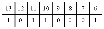
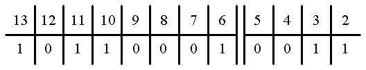
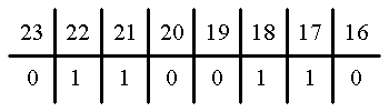
The SCSI bus 10 is supplemented by a multi-bit address bus generally designated with reference numeral 25 which conveys physical device addresses. Bus 25 is coupled to a host device (not illustrated) which generates a multi-bit character termed an anchor pattern, which is applied to...


PUM


Abstract

An automatic addressing technique for flexibility specifying the individual physical addresses of a plurality of devices coupled to an information bus. An anchor pattern is applied to an address bus of a plurality of address taps sufficient to uniquely specify the numbered J of devices to be attached thereto. Each device is connected to a tap on the address bus, each tap having the same number of bits. A plurality of address transform elements are serially connected to the bus, each transform element being located between adjacent tap positions. Each transform element converts the address pattern coupled to its input to another pattern capable of uniquely specifying the next address in the desired sequence. A wide variety of address sequences are available for selection, with each particular address sequence automatically determined by the related specific anchor pattern. The transform elements are passive elements, and no jumpers or settable switches are required to specify the physical addresses when configuring or reconfiguring the system.

Description

BACKGROUND OF THE INVENTIONThis invention relates to addressing techniques used for bus oriented computer systems. More particularly, this invention relates to an automatic addressing technique for flexibly specifying the individual addresses of a plurality of devices coupled to an information bus.Bus oriented computer systems are known in which individual devices connected to an information bus are assigned unique addresses specifying the location of each device in a computer system. Typically, individual devices are provided with a mechanical, electrical or electromechanical device capable of being set to provide a unique address for the device. For example, in some known arrangements, each device is provided with jumper terminals which can be connected to an appropriate voltage (e.g., ground) in such a manner that the voltage level on the combined collection of jumper terminals uniquely specifies the physical address of that device, usually using a binary numbering system. In sti...

Claims


Application Information

Patent Timeline
Patent Type & Authority Patents(United States)
IPC IPC(8): G06F12/06G06F13/14
CPCG06F12/0676
Inventor SAVAGE, THOMAS WARREN
Owner COMPAQ COMP CORP
Why Eureka
Try Eureka