Apparatus for tracking the flow of video signals by incorportating patterns of machine readable signals which will appear at predetermined locations of a television picture

a technology of video signals and apparatuses, applied in the field of television facility management, can solve the problems of inability to reliably monitor the flow of such programs in real time, inability to achieve real-time, and limited automation of on-air programs, and achieve the effect of reliably detection and identification

Inactive Publication Date: 2003-02-18
XL TRANSISTORS LIMITED LIABILITY
View PDF35 Cites 6 Cited by
  • Summary
  • Abstract
  • Description
  • Claims
  • Application Information

AI Technical Summary

Benefits of technology

A more specific object of the invention is to provide the video signals of each program with information which identifies the program and which can be decoded in a manner to be supplied to a computer system, thereby allowing real time management of a television facility.
The elements, or icons, employed to provide information in accordance with the present invention have the capability of retaining their information content even when the video signals in which they are contained are subjected to the various shifts and distortions mentioned above. The icons are constituted by simple patterns which have sufficient redundancy to assure reliable detection even after having been subjected to vertical and horizontal displacements of the type described above. In order to assure reliable decoding even if the icons have been subjected to analog level quantizing errors, each picture frame includes, in a defined area, a specific reference icon having regions which represent picture black, white and gray levels. The difference between the known values of these levels and the pixel values encountered when reading the reference icon gives an indication of the magnitude of gain and linearity errors which occurred subsequent to encoding. This information can be used as offsets in reading the icons recovered from the other three icon areas of a picture frame.
More specifically, the invention enables the problems relating to picture element position shifts and analog signal distortion to be overcome by using icon patterns which can be reliably detected and identified with the aid of currently available technology, employing fuzzy logic, even in the presence of high levels of noise or distortion. As opposed to detection techniques employing the classic Boolean logic, where each signal element can have only one of two values, 0 or 1, fuzzy logic can associate each signal element with a value in a substantially continuous range between 0 and 1. Therefore, fuzzy logic pattern recovery does not rely on a perfect match. It returns a value as to the closeness of a match. Reasonable amounts of noise or distortion do not hamper symbol recovery when the icons are constituted by patterns within parameters contemplated by the present invention, giving the system a robustness not found in Boolean based information systems.

Problems solved by technology

Up to the present, no system or procedures have been available to reliably monitor the flow of such programs in real time.
In other words, this procedure only allows the required determination to be made offline and hence not in real time.
In addition, some limited automation of on-air programs has been attempted.
However, to date, the capability of such systems is limited because, generally, they are not capable of automatically identifying the programs which are being routed through, or are stored in, a facility.

Method used


Image

  • Apparatus for tracking the flow of video signals by incorportating patterns of machine readable signals which will appear at predetermined locations of a television picture
  • Apparatus for tracking the flow of video signals by incorportating patterns of machine readable signals which will appear at predetermined locations of a television picture
  • Apparatus for tracking the flow of video signals by incorportating patterns of machine readable signals which will appear at predetermined locations of a television picture

Examples


Embodiment Construction

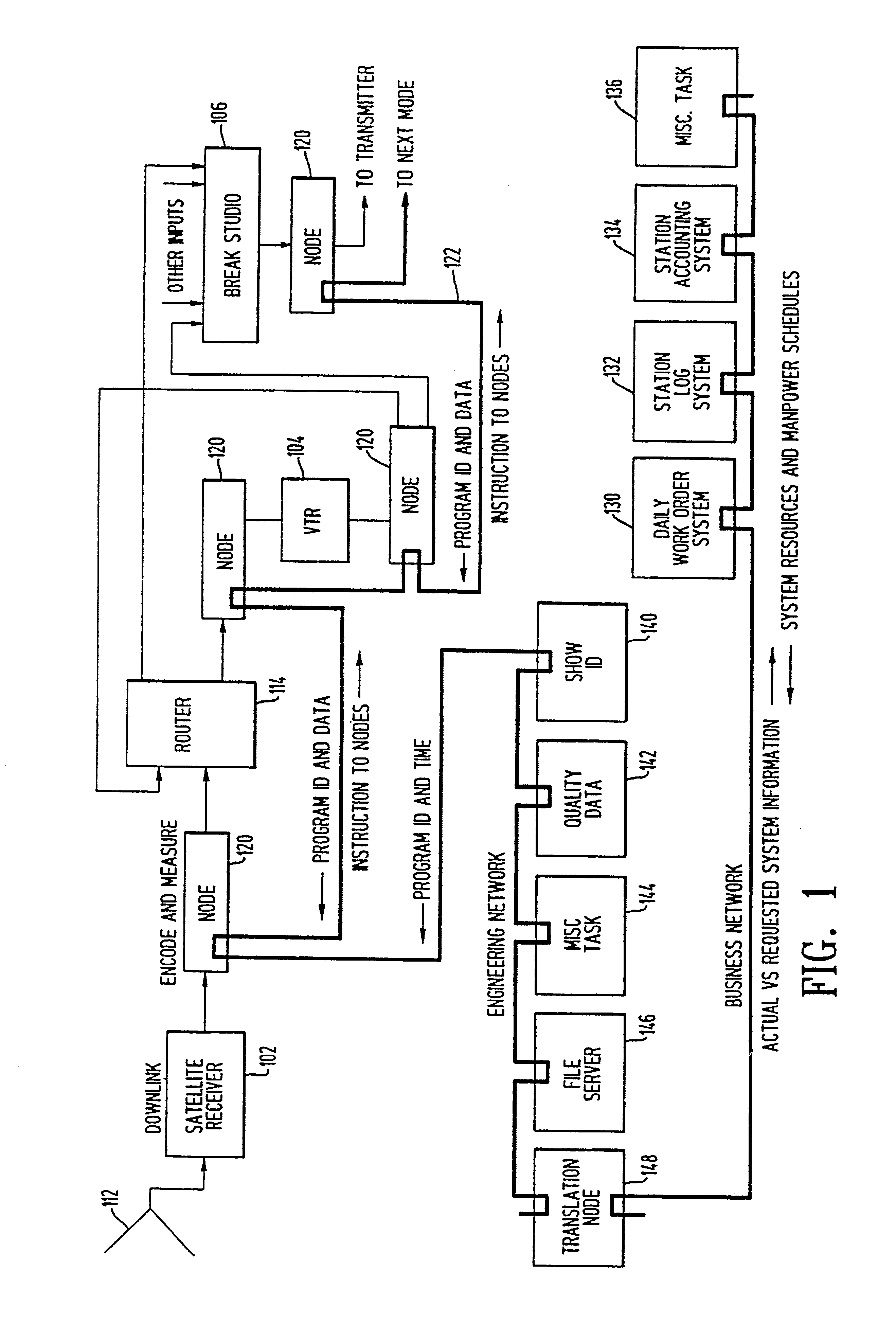
FIG. 1 is a block diagram of a typical television distribution system which can be constructed in accordance with the present invention. The configuration of the exemplary system has been selected arbitrarily, simply for purposes of illustration. It is to be understood that any television program distribution system, regardless of its complexity and / or geographic extent, could serve as a basis for implementation of the invention. Furthermore, although the illustrated embodiment is described in connection with the N.T.S.C. standard, it should be appreciated that the present invention is applicable to all video formats, both those in present use as well as those formats which will be developed in the future.

The system illustrated in FIG. 1 includes television signal processing components, such as a satellite receiver 102, a video tape recorder 104 and a television signal processing and control area, known in the industry as a break studio, 106. Satellite receiver 102 is connected to a...


PUM


Abstract

Method and apparatus for encoding and decoding video signals for identification, editing, modifying, cuing, routing, distributing, switching, activating and controlling the video signals. One of the many applications is a television program distribution system including a plurality of units through which the television programs flow, by operating a first signal processing unit connected within the system for adding signal elements to the video signal of a program in order to add patterns of symbols to the television picture such that the symbols are disposed at predetermined locations of the television picture and a plurality of successive patterns constituting a code uniquely identifying the program; and a second signal processing unit connected within the system for detecting signal elements previously added to a video signal and for producing, in response to such detection, an identification of the program which included the video signal.

Description

BACKGROUND OF THE INVENTIONThe present invention relates to the management of television facilities, particularly for the purpose of tracking television programs stored, in recorded form, and being transmitted within, the facility, as well as programs being received and transmitted by the facility.Television programs, prior to broadcast or transmission over a cable system, may be conducted over a wide variety of paths within a facility and between facilities. Up to the present, no system or procedures have been available to reliably monitor the flow of such programs in real time. As a consequence, those managing such facilities generally must rely on the assumption that all operating personnel have taken the necessary steps to route the programs in the desired manner. At present, one of the most feasible procedures for determining what has actually been broadcast or distributed by a cable system is to make an off-air recording of all programs which have been broadcast or distributed...

Claims


Application Information

Patent Timeline
Patent Type & Authority Patents(United States)
IPC IPC(8): H04H9/00H04N7/08H04H7/00H04H7/04H04N5/765H04N5/268H04N17/00H04N5/262H04H1/00H04H20/31H04H60/58
CPCH04H20/14H04H20/31H04H60/58H04N5/262H04N5/268H04N5/765H04N7/08H04N17/00
Inventor LEGATE, KIM R.
Owner XL TRANSISTORS LIMITED LIABILITY
Why Eureka
Try Eureka