Bi-directional overrunning clutch

a bi-directional, electromechanical technology, applied in the direction of fluid couplings, inter-engaging clutches, gearing, etc., can solve the problems of cumbersome vehicles, vehicle stopping, and more expensive limited slip differentials

a bi-directional, electromechanical technology, applied in the direction of fluid couplings, inter-engaging clutches, gearing, etc., can solve the problems of cumbersome vehicles, vehicle stopping, and more expensive limited slip differentials

USRE38012E1Inactive Publication Date: 2003-03-04HILLIARD

Image

  • Bi-directional overrunning clutch
  • Bi-directional overrunning clutch
  • Bi-directional overrunning clutch

Examples


second embodiment

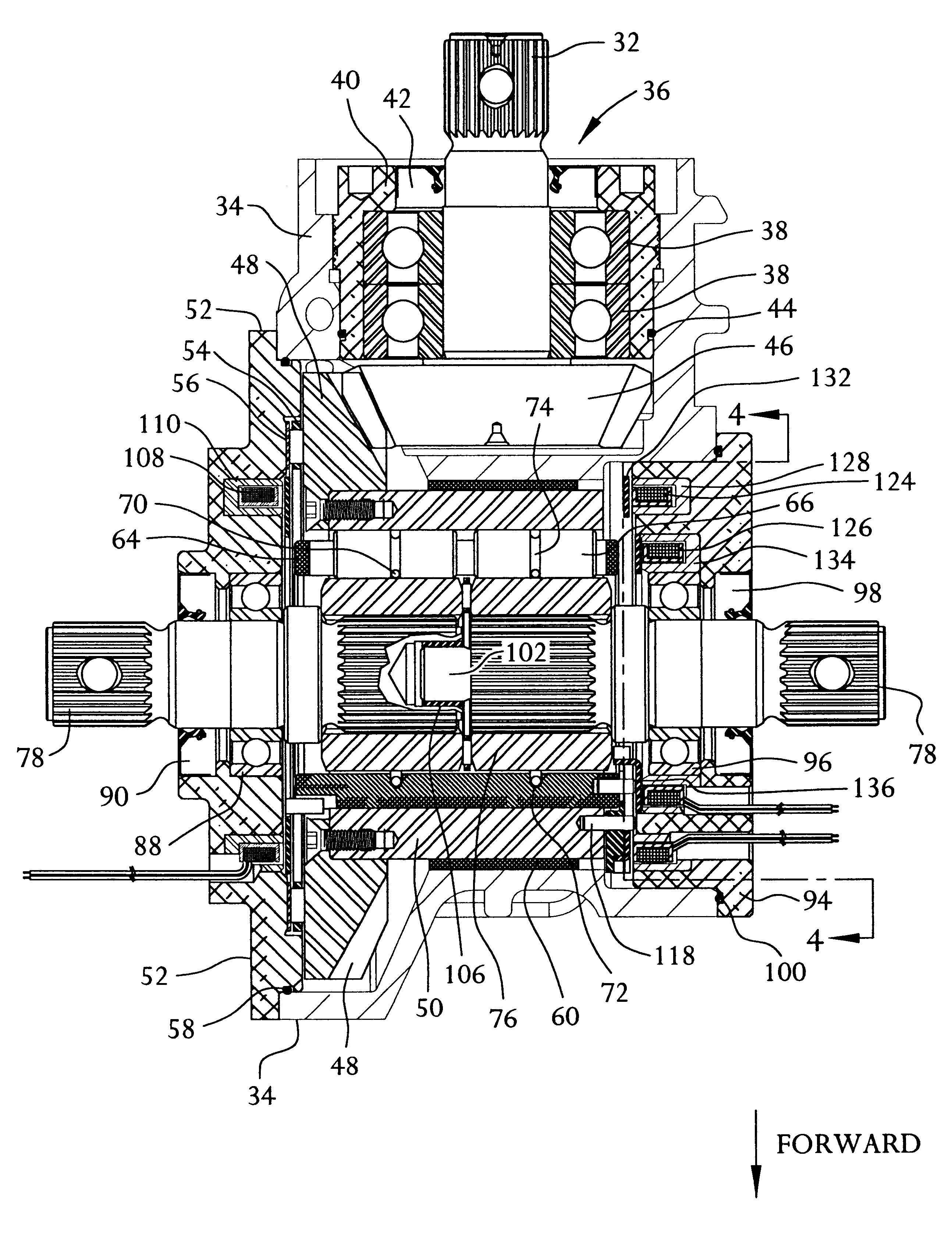
the invention is shown in FIGS. 7 and 8 wherein a toggle system is incorporated into the right side of the differential housing 34. In this embodiment, the tangs 114 on the first armature plate 112 do not engage with slots 116 formed in the roll cage 64. Instead, at least one, and more preferably three, toggle levers 200 which are pivotally mounted to the clutch housing 50 and engaged with the roll cage 64 for causing the roll cage 64 to advance and retard.

More particularly, each toggle lever 200 has an inner end 200.sub.A and an outer end 200.sub.B. The outer end 200.sub.B is pivotally mounted to the clutch housing 50 via a dowel pin 202. The toggle lever 200 also has a slotted opening 204 located approximately midway along its length. The slotted opening 204 is sized to slidingly engage with a protruding pin 206 which extends outward from a flange 208. The flange 208, in turn, is mounted to the roll cage 64 by pins 210. Since the flange 208 is pinned to the roll cage 64, it rotate...


PUM


Abstract

A bi-directional overrunning clutch is disclosed for controlling torque transmission between a secondary drive shaft and secondary driven shafts. The overrunning clutch includes a pinion input shaft in a differential housing that engages with a clutch housing rotatably disposed within the differential housing. At least one race is located adjacent to the clutch housing and is engaged with an output shaft. A cage is located between the race and the clutch housing. The cage is movable with respect to the clutch housing. A <DEL-S DATE="20030304" ID="DEL-S-00001" / >first<DEL-E ID="DEL-S-00001" / > coil is mounted within the differential housing adjacent to the cage and is adapted to produce an electromagnetic field when energized which causes the cage to drag with respect to the clutch housing. The dragging of the cage with respect to the clutch housing positions <INS-S DATE="20030304" ID="INS-S-00001" / >rolls within <INS-E ID="INS-S-00001" / >the cage to engage the clutch housing with the race when wheels on a primary drive shaft lose traction. <DEL-S DATE="20030304" ID="DEL-S-00002" / >A<DEL-E ID="DEL-S-00002" / > <INS-S DATE="20030304" ID="INS-S-00002" / >If desired a <INS-E ID="INS-S-00002" / >second coil <DEL-S DATE="20030304" ID="DEL-S-00003" / >is<DEL-E ID="DEL-S-00003" / > <INS-S DATE="20030304" ID="INS-S-00003" / >may be <INS-E ID="INS-S-00003" / >mounted within the differential housing adjacent <DEL-S DATE="20030304" ID="DEL-S-00004" / >adjacent<DEL-E ID="DEL-S-00004" / > to the cage. The second coil is adapted to produce an electromagnetic field when energized which advances cage with respect to the clutch housing causing the clutch housing to engage with the races. When the second coil is activated, the output shaft drives the pinion input shaft producing engine braking. An electronic control system is utilized to control the energizing of the coils.

Description

FIELD OF THE INVENTIONThe present invention relates to clutches and, more particularly, to a bi-directional electromechanical overrunning clutch for providing four wheel drive capability.BACKGROUND OF THE INVENTIONThe increased demand in recent years for off-road and all terrain vehicles has led to tremendous developments in those types of vehicles. Many of the developments have centered around making the vehicle more adaptable to changing road conditions, e.g., dirt roads, pavement and gravel. As the road terrain changes, it is desirable to vary the driving capabilities of the vehicle to more efficiently navigate the new terrain. Prior four-wheel drive and all terrain vehicles were cumbersome since they required the operator to manually engage and disengage the secondary drive shaft, e.g., by stopping the vehicle to physically lock / unlock the wheel hubs. Improvements in vehicle drive trains, such as the development of automated systems for engaging and disengaging a driven axle, el...

Claims


Application Information

Patent Timeline
04 Mar 2003
Publication
USRE38012E1
IPC
F16D41/064; F16D41/00; F16D41/08; F16D27/10; B60K23/08
CPC
F16D27/10; F16D41/064; F16D41/088; B60K23/08; Y10T74/19005; F16D2027/005; F16H48/12
Inventors
OCHAB, DAVID C.; UPDYKE, JOHN R.