Apparatus for making nonwoven fabrics having raised portions

a technology for nonwoven fabrics and accessories, applied in the direction of pattern making, manufacturing tools, transportation and packaging, etc., can solve the problems of complex product creation, high cost, and inability to meet the needs of customers, and achieve the effect of reducing labor intensity, reducing labor intensity, and increasing production cos

Inactive Publication Date: 2003-05-06
PGI POLYMER
View PDF13 Cites 32 Cited by
  • Summary
  • Abstract
  • Description
  • Claims
  • Application Information

AI Technical Summary

Problems solved by technology

Originally, this process was obtained through tedious hand labor, painstakingly applying fine stitches that had the cumulative effect of building up a region of the background fabric according to some particular pattern.
While rich in appearance, these products were complicated to create and costly to produce.
Most nonwoven fabrics are flat and visually uninteresting.
The prior art nonwoven fabrics made with these known patterning processes do not have clear, well defined raised portions and therefore the desired patterns are difficult to see.
In addition, the raised portions of prior art embossed nonwoven fabrics are not dimensionally stable and their raised portions lose their three-dimensional structure when stressed, as for example, when they are handled or laundered.

Method used


Image

  • Apparatus for making nonwoven fabrics having raised portions
  • Apparatus for making nonwoven fabrics having raised portions
  • Apparatus for making nonwoven fabrics having raised portions

Examples


example 1

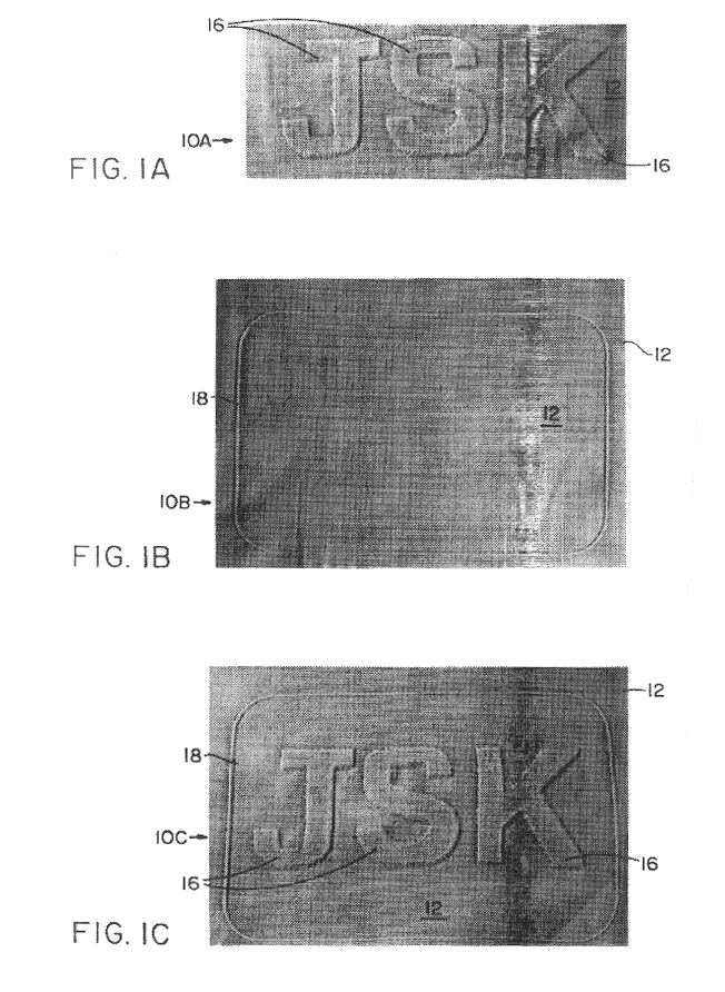
This example shows the production of a topographical support member which can be used to produce nonwoven fabric 10C of FIG. 1C. The precursor topographical support member is made of acetal and has the topographical pattern of peaks, valleys and apertures shown in FIG. 13 of the accompanying drawings. The precursor topographical support member was made by the laser drilling process disclosed in commonly assigned copending U.S. patent application Ser. No. 08 / 307,203, now U.S. Pat. No. 5,585,017, filed Sep. 16, 1994, the title of which is "Defocused Laser Drilling Process For Making Fabric Forming Device" and the disclosure of which is hereby incorporated by reference. The support member of this Example 1 was made on the apparatus of FIG. 16 using the precursor support member just mentioned and the laser ablation process described hereinabove. The precursor support member was mounted on mandrel 821. The computer graphic file used to control the laser ablation process was that shown in...

example 2

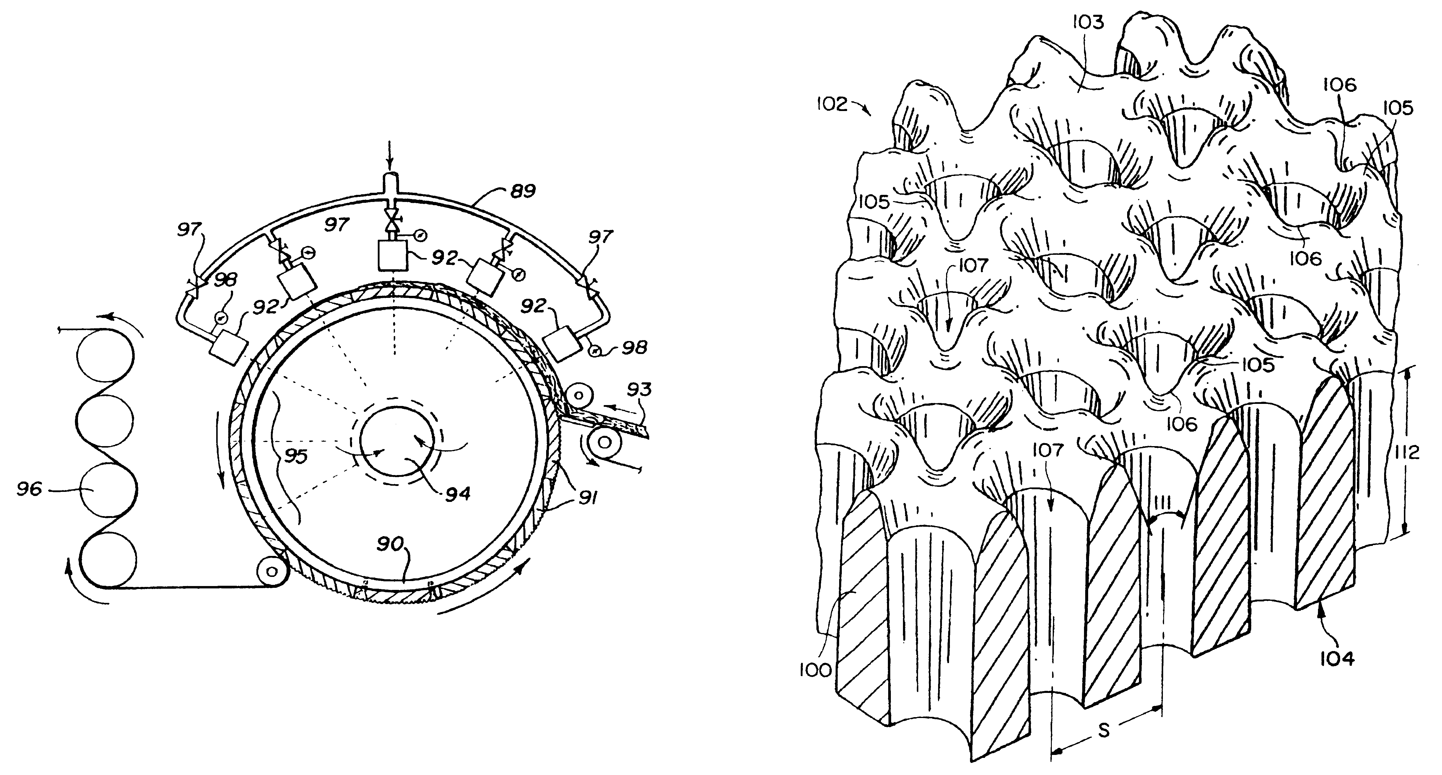
This example illustrates the production of nonwoven fabric 10C shown in FIG. 1C using the topographical support member made in accordance with Example 1. The topographical support member of Example 1 was removed from mandrel 821 of the apparatus shown in FIG. 16 and was mounted on drum 90 of the apparatus shown in FIG. 12.

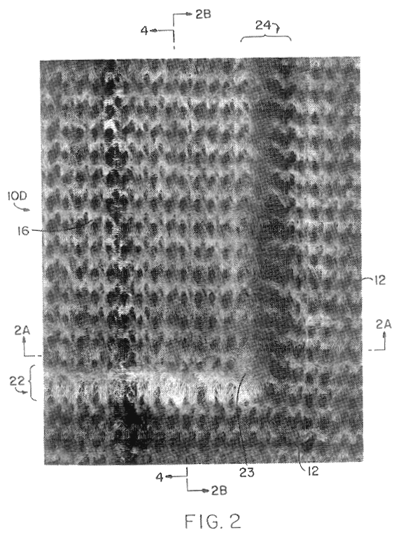
A fibrous web consisting entirely of staple-length cotton fibers and weighing 1.2 ounces per square yard was made by combining a 0.6 ounce per square yard 100% cotton web made by a conventional carding process and a 0.6 ounce per square yard 100% cotton web made by a conventional air laying process. In the specific example being discussed, the carded web and the air laid web were combined by positioning the air laid web on top of the carded web. It will be understood that the carded web could, if desired, be positioned on top of the air laid web.

The aforementioned 1.2 oz / sq yd 100% cotton web was lightly pre-entangled using a conventional flat-belt entangling appar...


PUM

PropertyMeasurementUnit
angleaaaaaaaaaa
diameteraaaaaaaaaa
distanceaaaaaaaaaa

Abstract

A topographical support member and a method of forming a topographical support member for use in producing nonwoven fabrics with raised portions, especially intaglio and slub type portions. The topographical support member comprises a body having a top surface including a first micro-sized topographical pattern and a pattern of apertures extending through the body. At least one macro-sized region recessed below the top surface is provided. The micro-sized pattern produces a background portion of the fabric and the macro-sized recessed regions produce the raised portions of the fabric. Multiple levels may be provided in the macro-sized region to produce multiple level raised portions.

Description

BACKGROUND OF THE INVENTIONTraditional fabrics have, for centuries, been decorated and had their surface texture modified by embroidery and other needle arts. Originally, this process was obtained through tedious hand labor, painstakingly applying fine stitches that had the cumulative effect of building up a region of the background fabric according to some particular pattern. The resulting product had a base fabric, comprised of threads or yarns, woven or knitted according to some pattern, a raised region formed by a collection of threads in some stitch pattern, and an overall pattern of these raised regions determined by their respective size, shape, orientation and placement. While rich in appearance, these products were complicated to create and costly to produce.Most nonwoven fabrics are flat and visually uninteresting. In some instances, nonwoven fabrics are embossed or printed with some sort of design to provide visual interest. In other instances, nonwoven fabrics are provid...

Claims


Application Information

Patent Timeline
Patent Type & Authority Patents(United States)
IPC IPC(8): B23K26/00B23K26/38D04H1/46D04H17/00D04H18/04
CPCB23K26/381D04H1/465D04H18/04B23K26/4055Y10T428/24273Y10T428/24355Y10T428/24479B23K26/382B23K2103/38B23K2103/50D04H1/495
Inventor JAMES, WILLIAM A.KELLY, WILLIAM G. F.
Owner PGI POLYMER
Why Eureka
Try Eureka