
Inverted board mounted electromechanical device

a technology of electromechanical devices and inverters, which is applied in the direction of relays, cross-talk/noise/interference reduction, and association of printed circuit non-printed electric components, can solve the problems of low overall profile of circuit boards, and achieve the effect of convenient surface mounting

Inactive Publication Date: 2004-01-13
COTO TECH
View PDF58 Cites 13 Cited by
  • Summary
  • Abstract
  • Description
  • Claims
  • Application Information

AI Technical Summary

Benefits of technology

The present invention preserves the advantages of prior art electromagnetic switch devices, such as reed relays. In addition, it provides new advantages not found in currently available switching devices and overcomes many disadvantages of such currently available devices.
Another object of the present invention is to provide a reed switch package that can be easily surface mounted to a main circuit board.

Problems solved by technology

As a result, the reed relay component is recessed below the surface of the main circuit board resulting in an overall low profile circuit board.

Method used


Image

  • Inverted board mounted electromechanical device
  • Inverted board mounted electromechanical device
  • Inverted board mounted electromechanical device

Examples


Embodiment Construction

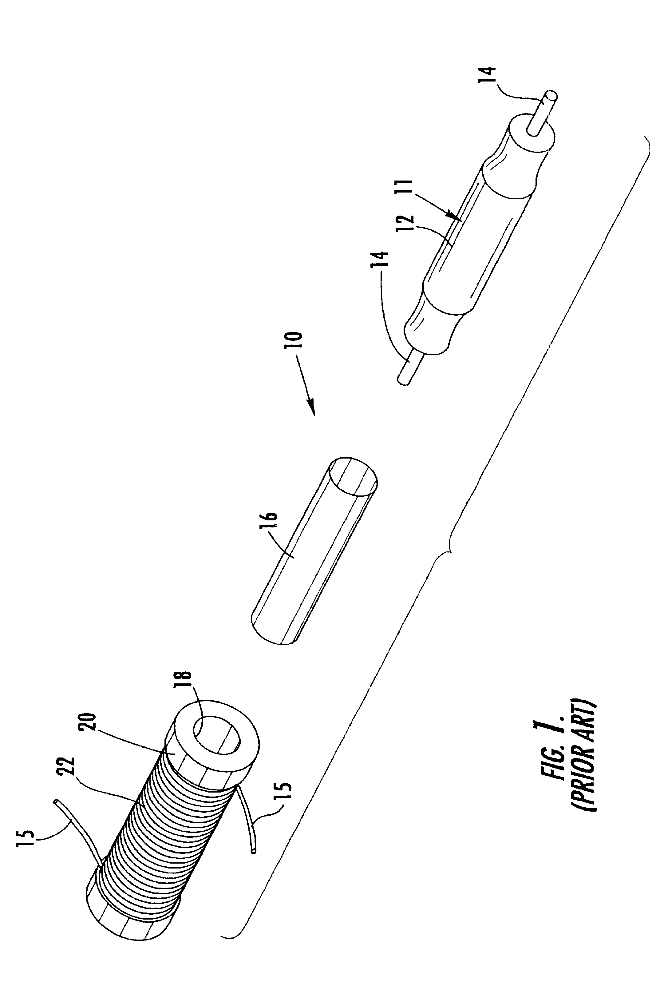
Turning first to FIG. 1, a perspective view of a prior art reed switch configuration 10 is shown. A known reed switch 11 includes a glass envelope 12 as well as two signal leads 14 emanating from opposing ends of the reed switch 11 and coil termination leads 15. The construction of a reed switch 11 is so well known in the art, the details thereof need not be discussed. A shield conductor 16, commonly made of brass or copper, is provided in the form of a cylindrical sleeve which receives and houses the reed switch 11. The reed switch 11 and shield 16 are housed within the central bore 18 of a bobbin or spool 20. About the bobbin 20 is wound a conductive wire 22. As a result, a co-axial arrangement is formed to protect the reed switch 11 device and to control the impedance of the environment and to improve the overall transmission of the signal. The reed switch 11, shield conductor 16 and bobbin 20 are shown in general as cylindrical in configuration. It should be understood that vari...


PUM


Abstract

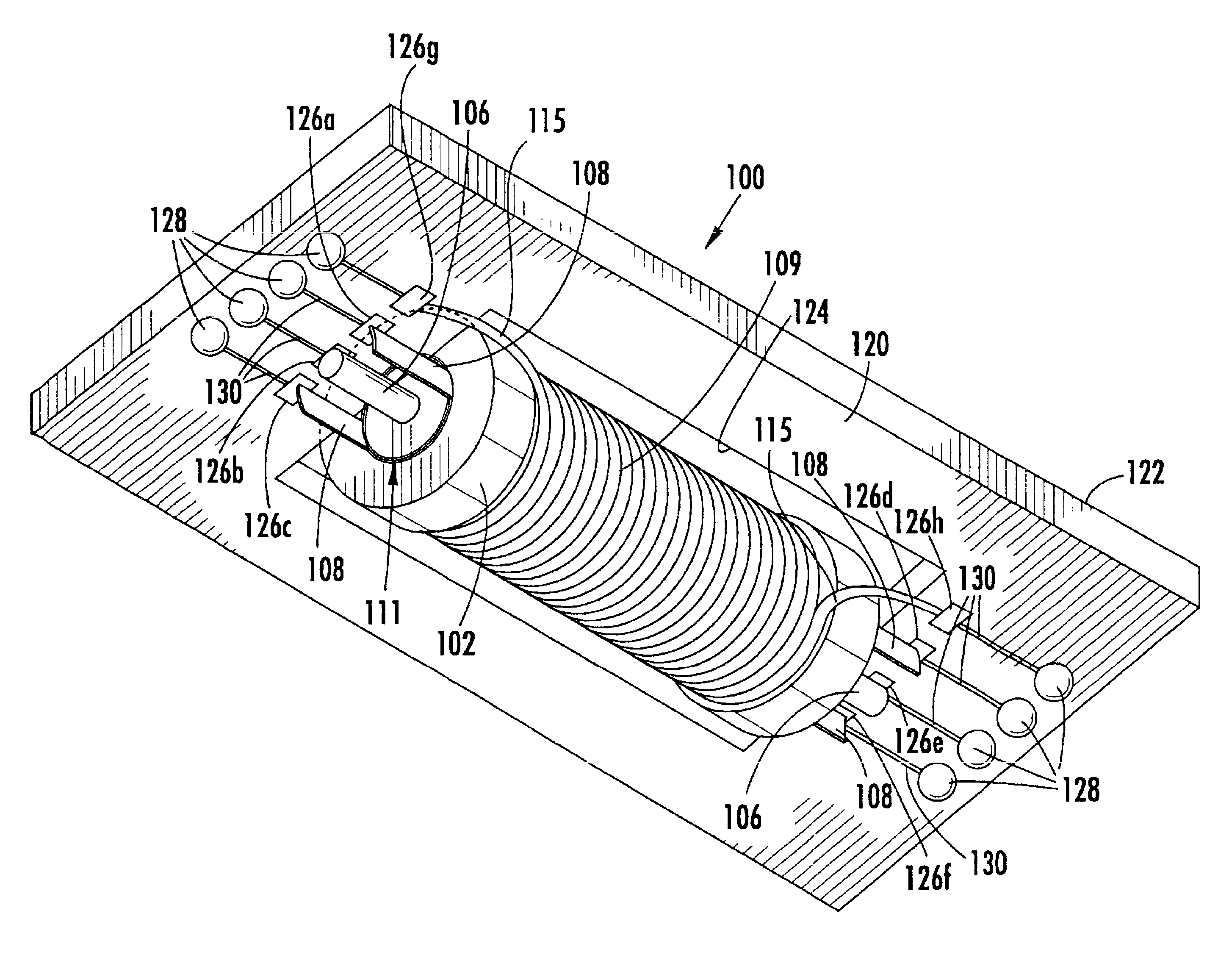
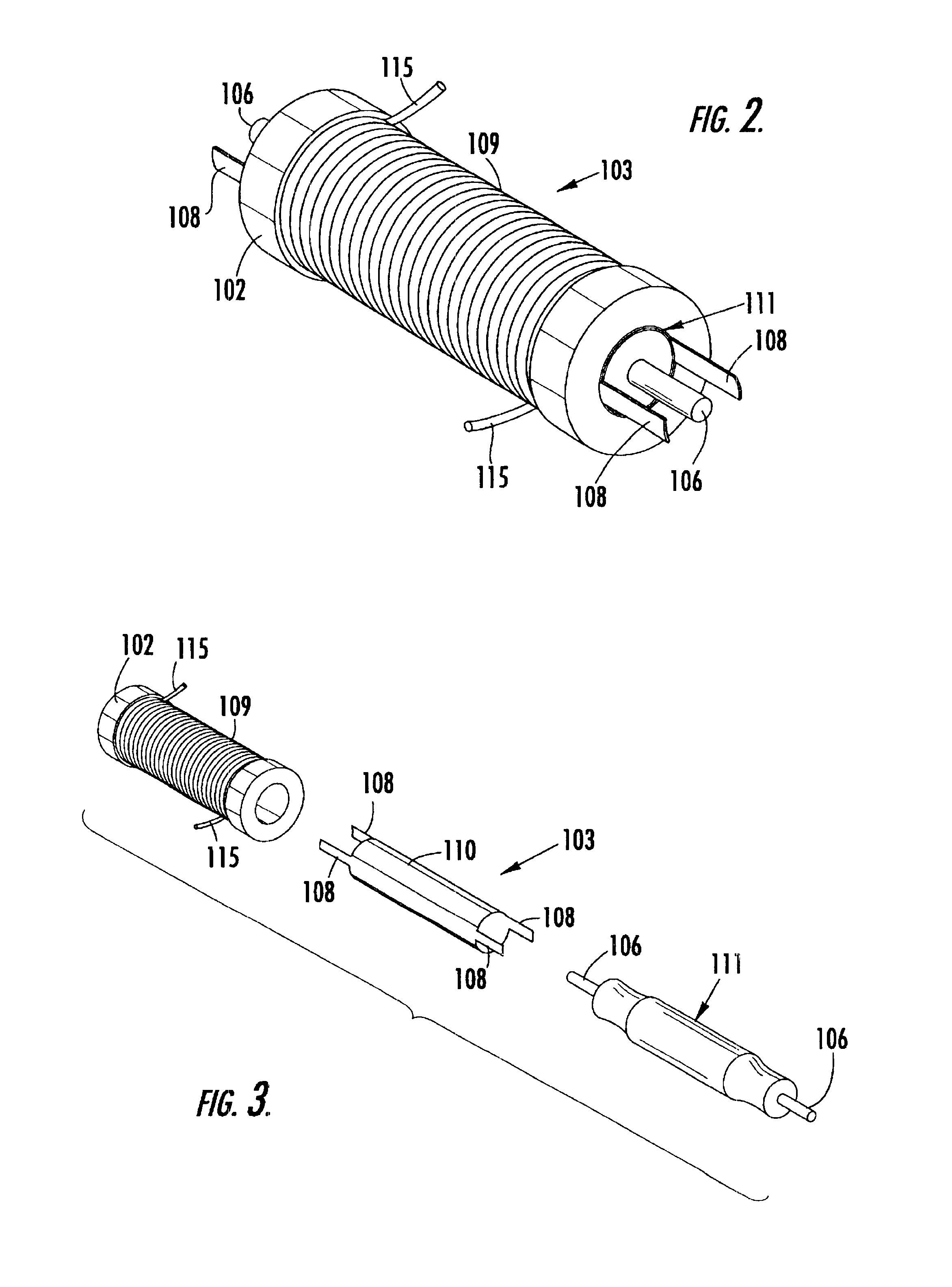
A new board mounted electromechanical device is provided that mounts to a relay substrate to form a low profile reed relay. The reed relay is electrically connected to the electrical contacts via a signal traces and additional electrical traces located on the same side of the relay substrate which connect to the relay's signal and shielding. Additional traces on both sides of the signal traces of the reed relay provide a co-planar wave guide to maintain the desired impedance of the signal path. The reed relay is mounted in an inverted manner into a cut-out in the main circuit board so that the other portion of the reed relay itself is sits within the cut-out in the main circuit board. As a result, the reed relay component is recessed below the surface of the main circuit board resulting in an overall low profile circuit board.

Description

The present invention relates generally to switching devices. More specifically, the present invention relates to improved packaging and circuit integration for electromagnetic devices, such as reed switches and electromagnetic devices such as reed relays.Electromagnetic relays have been known in the electronics industry for many years. Such electromagnetic relays include the reed relay which incorporates a reed switch. A reed switch is a magnetically activated device that typically includes two flat contact tongues which are merged in a hermetically sealed glass tube filled with a protective inert gas or vacuum. The switch is operated by an externally generated magnetic field, either from a coil or a permanent magnet. When the external magnetic field is enabled, the overlapping contact tongue ends attract each other and ultimately come into contact to close the switch. When the magnetic field is removed, the contact tongues demagnetize and spring back to return to their rest positi...

Claims


Application Information

Patent Timeline
IPC IPC(8): H01H51/00H01H51/28H05K1/14H05K1/18H05K1/02
CPCH01H51/281H05K1/0219H05K1/141H05K1/182H05K2201/049H05K2201/09072H05K2201/10083H05K2201/10477
Inventor MARTICH, MARK E.
Owner COTO TECH
Learn More