Current detection resistor
a current detection and resistor technology, applied in resistor details, base element modifications, instruments, etc., can solve the problems of inability to meet the demand of miniaturization of equipment, inability to accurately detect current in resistors, and inability to meet the demands of high-adjustable current detection, etc., to achieve easy surface mounting, improve heat radiation, and high accuracy
- Summary
- Abstract
- Description
- Claims
- Application Information
AI Technical Summary
Benefits of technology
Problems solved by technology
Method used
Image
Examples
first embodiment
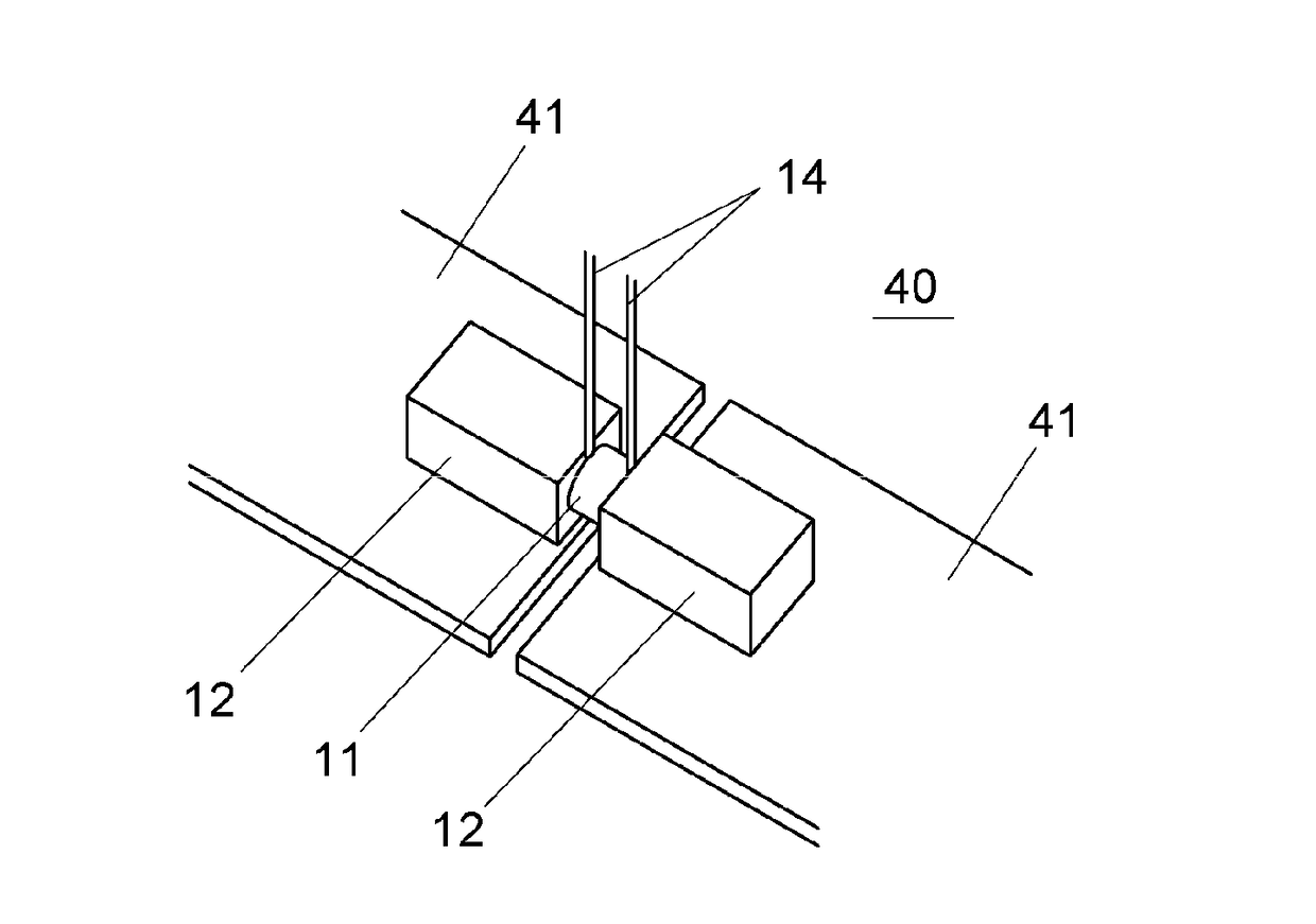
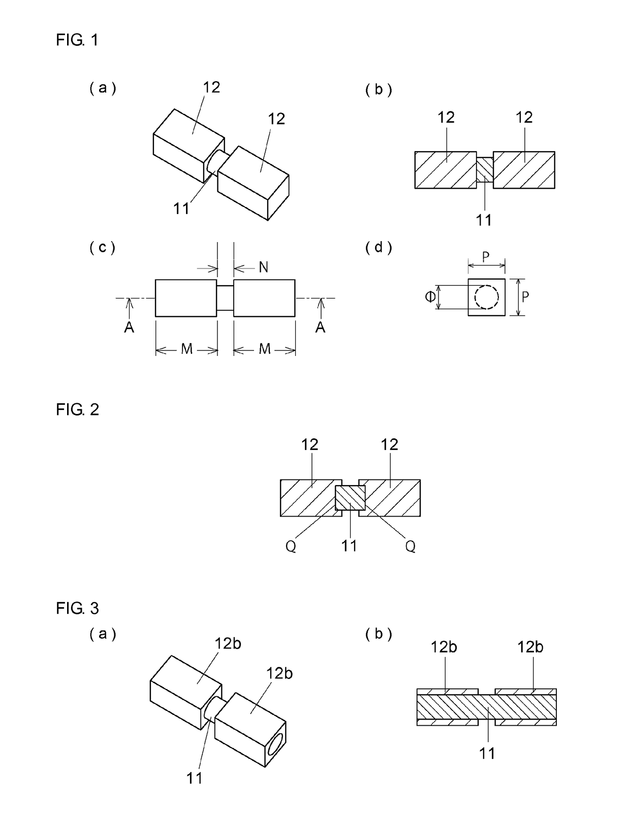
[0025]FIG. 1 shows structures of the resistor of first embodiment of the invention. The resistor includes a resistor body 11 and at least a pair of electrodes 12. The resistive alloy material such as Cu—Mn—Ni system alloy and Cu—Ni system alloy etc., which are generally used for the resistor, can be used for resistor body 11. As for electrodes 12, Cu etc. that is metal material of high electric conductivity, is used.
[0026]The resistor body 11 is configured to be a pillar-shape having diameter of 4 mm or less disposed between the electrodes 12. By making the resistor body thin diameter, resistance change by skin effect when high frequency current being applied, is inhibited, then current detection of high accuracy becomes possible for currents including high frequency components in some degree. That is, as to current detection resistor, in which detection of direct current is assumed to be basic, decrease of current path by skin effect is not substantially caused in some degree of hi...
third embodiment
[0033]FIG. 3 shows the resistor of third embodiment of the invention. In the embodiment, electrode 12b is formed to be like the pipe, and the resistor has the structure that both end portions of thin resistor body 11 is penetrated through the electrode 12b. In the embodiment, by making diameter of resistor body 11 thin, resistance variation according to skin effect when high frequency current flowing can be inhibited.
[0034]And, since the resistor has the structure that resistor body penetrates through inside of electrode 12b, application of swaging processing becomes possible, as mentioned later, and application of thermal fitting also can be possible. Here, thermal fitting is a method that expanding a hole of electrode like the pipe by applying heat, inserting resistor body into the hole and cooling, and then electrode and resistor body becoming closely contacted and fixed by the electrode like the pipe shrinking.
fourth embodiment
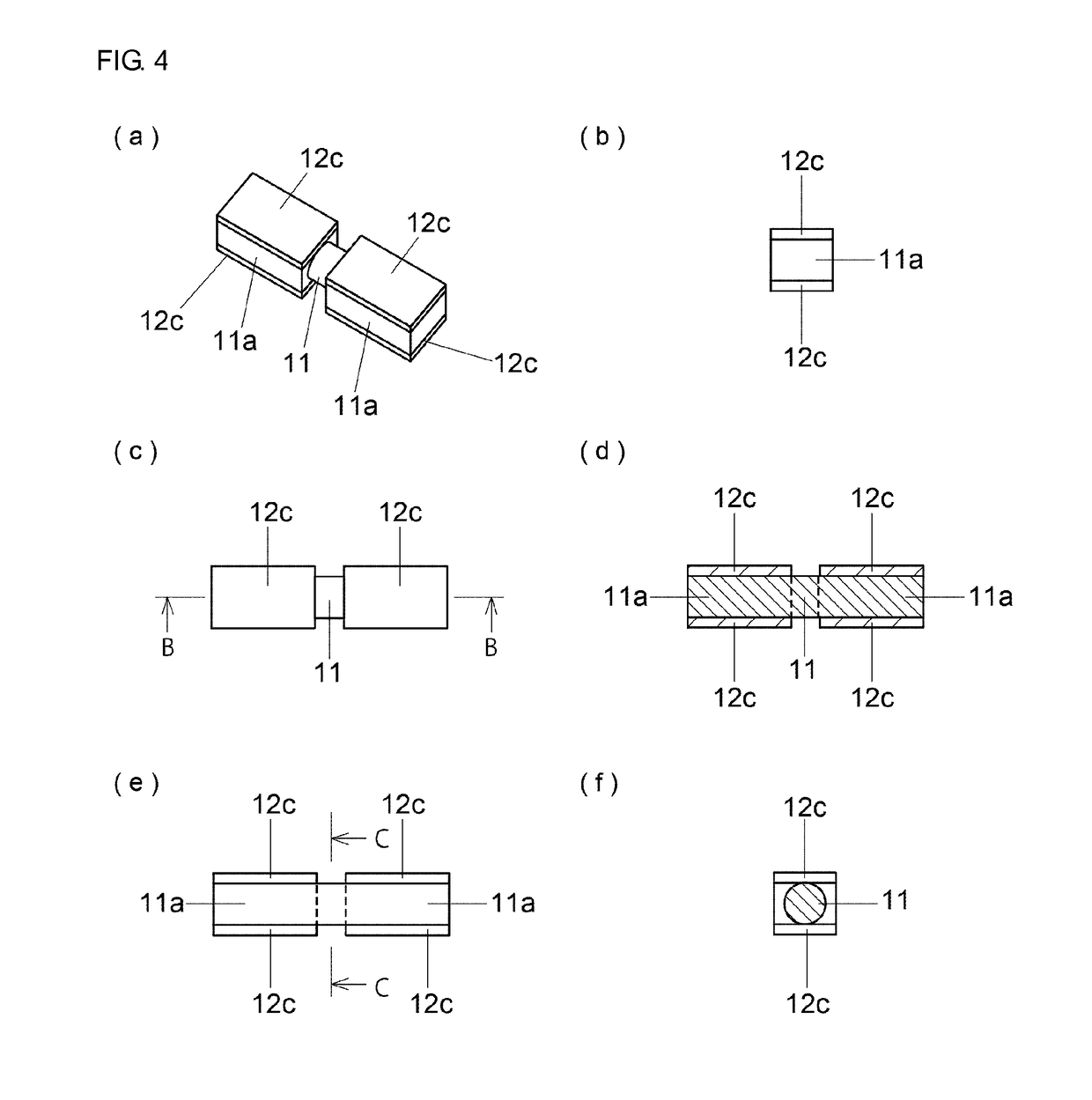
[0035]FIG. 4 shows the resistor of fourth embodiment of the invention. In the embodiment, the resistor body is configured by columnar resistor body 11 at central portion and flat resistance bodies 11a at both ends thereof. Plate-shaped electrode 12c is provided at both upper and lower surfaces of flat resistor body 11a. Therefore, the structure that has thin columnar resistor body at central portion and square pillar electrodes at both ends thereof is common with above-mentioned embodiments. In the embodiment, by having square pillar electrode 12c, advantages such as easy surface mounting and improvement of heat radiation are common with above-mentioned embodiments.
[0036]FIG. 5 shows manufacturing method of the resistor of first embodiment of the invention. First, strip material 20, which clad-bonds strip material for electrode 20a, strip material for resistor 20b, and strip material for electrode 20a, is prepared as shown in (a). Strip material 20 may be formed by welding such as l...
PUM
 Abstract
Description
Claims
Application Information
 - R&D
- Intellectual Property
- Life Sciences
- Materials
- Tech Scout
- Unparalleled Data Quality
- Higher Quality Content
- 60% Fewer Hallucinations
Browse by: Latest US Patents, China's latest patents, Technical Efficacy Thesaurus, Application Domain, Technology Topic, Popular Technical Reports.
© 2025 PatSnap. All rights reserved.Legal|Privacy policy|Modern Slavery Act Transparency Statement|Sitemap|About US| Contact US: help@patsnap.com


