Eureka AIR delivers breakthrough ideas for toughest innovation challenges, trusted by R&D personnel around the world.

Automatic visual inspection system

Inactive Publication Date: 2005-03-22
ORBOTECH LTD
View PDF30 Cites 19 Cited by
  • Summary
  • Abstract
  • Description
  • Claims
  • Application Information

AI Technical Summary

Benefits of technology

According to the present invention, a binary map of an object having edges is produced by first producing a digital grey scale image of the object with a given resolution, and processing the grey scale image to produce a binary map of the object at a resolution greater than said given resolution. If the ultimate resolution required is, for example, one mil (0.001 inches), then, the resolution of the digital grey scale image can be considerably less than one mil, and may be, for example, three mils. The larger than final pixel size involved in acquiring data from an object permits objects to be scanned faster, and either reduces the amount of light required for illuminating the object or permits the same amount of light to be used thus decreasing the effect on accuracy of noise due to statistical variations in the amount of light. Finally, increasing the pixel size during data acquisition improves the depth of field and renders the system less sensitive to variations in the thickness of the boards being tested.

Problems solved by technology

The larger than final pixel size involved in acquiring data from an object permits objects to be scanned faster, and either reduces the amount of light required for illuminating the object or permits the same amount of light to be used thus decreasing the effect on accuracy of noise due to statistical variations in the amount of light.

Method used


Image

  • Automatic visual inspection system
  • Automatic visual inspection system
  • Automatic visual inspection system

Examples


Embodiment Construction

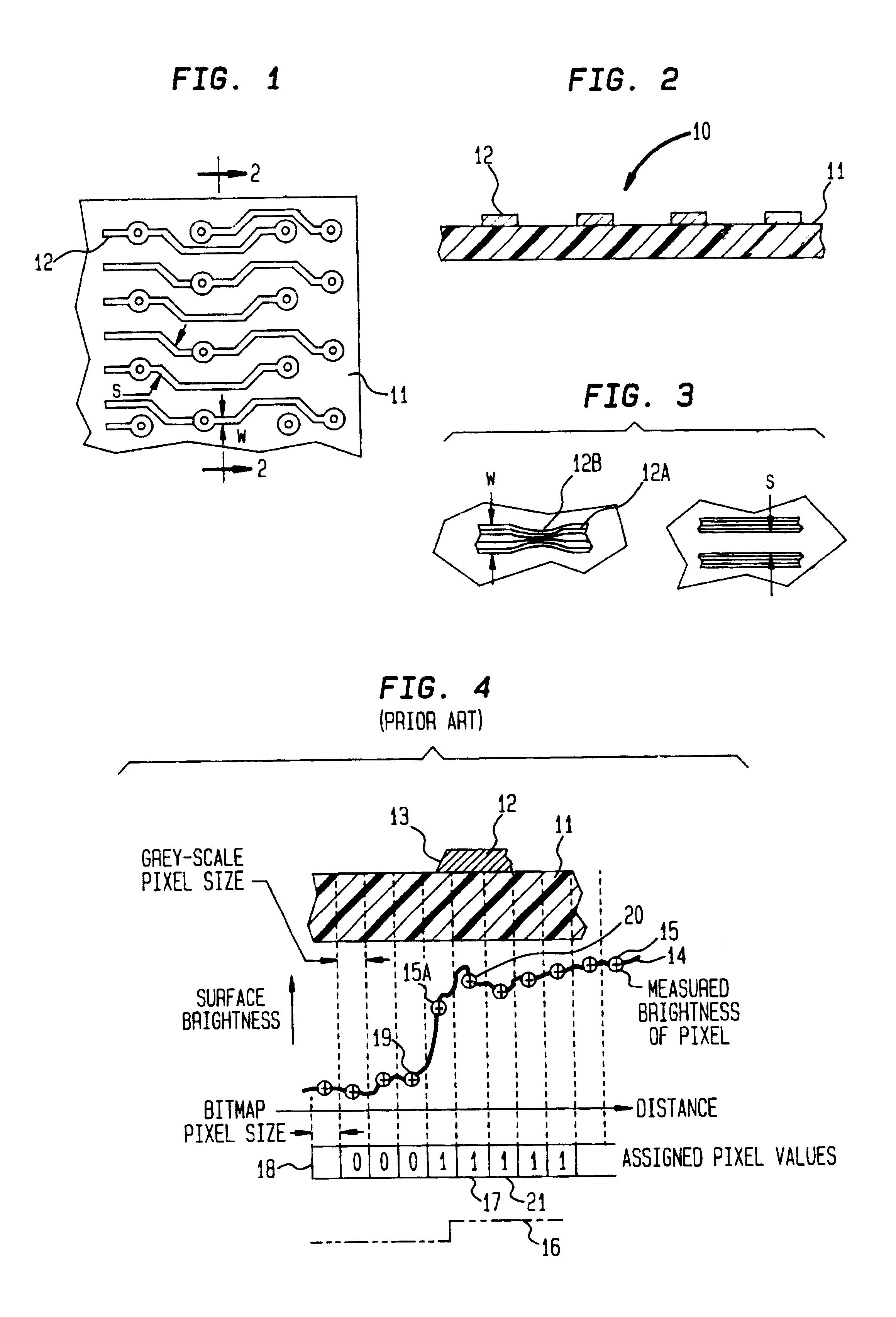
Referring now to the drawing, reference numeral 10 designates a conventional printed circuit board comprising substrate 11 on one surface of which are deposited conductive tracks or lines 12 in a manner well known in the art. A typical board may have 3 mil lines, and spacing between lines of a comparable dimension.

As is well known, the technique of depositing lines 12 on substrate 11 involves a photographic and etching process which may produce a result shown in FIG. 3 where line 12a, of width w has a reduced portion at 12b. The cross section available for conduction in reduced portion 12b may be insufficient to permit proper operation of the electronic components associated with the printed circuit board; and for this reason a board having a line of a width less than some predetermined value would be rejected, or at least noted. As boards get more and more complex, detecting breaks in lines, or lines with reduced width, becomes more and more difficult.

The photoetching process invol...


PUM


Abstract

A binary map of an object having edges is produced by first producing a digital grey scale image of the object with a given resolution, and processing the grey scale image to produce a binary map of the object at a resolution greater than said given resolution. Processing of the grey scale image includes the step of convolving the 2-dimensional digital grey scale image with a filter function related to the second derivative of a Gaussian function forming a 2-dimensional convolved image having signed values. The location of an edge in the object is achieved by finding zero crossings between adjacent oppositely signed values. Preferably, the zero crossings are achieved by an interpolation process that produces a binary bit map of the object at a resolution greater than the resolution of the grey scale image. The nature of the Gaussian function whose second derivative is used in the convolution with the grey scale image, namely its standard deviation, is empirically selected in accordance with system noise and the pattern of the traces on the printed circuit board such that the resulting bit map conforms as closely as desired to the lines on the printed circuit board.

Description

TECHNICAL FIELD OF THE INVENTIONThis invention relates to automatic visual inspection systems, more particularly to systems for inspecting printed circuit boards, hybrid boards, and integrated circuits.BACKGROUND OF THE INVENTIONIn its simplest form, a printed circuit board or panel comprises a non-conductive substrate on one or both surfaces of which are deposited conductive tracks or lines in a pattern dictated by the design of the electronic equipment supported by the board. More complex boards are constructed by laminating a number of single panels into a composite or multi-layered board; and the use of the latter has increased dramatically in recent years in an effort to conserve space and weight.As component size has shrunk, component density on boards has increased with the result that line size and spacing have decreased over the years. Because of the “fine geometry” of modern boards, variations in line width and spacing have become more critical to proper operation of the b...

Claims


Application Information

Patent Timeline
IPC IPC(8): G06T5/00G06T7/00G06T5/20
CPCG06T3/403G06T7/0004G06T2200/28G06T2207/30141G06T7/12
Inventor CASPI, AMIRAMLAPIDOT, ZVI
Owner ORBOTECH LTD
Why Eureka
Eureka Blog
Learn More